Allegion Developer Portal
Allegion Developer Portal

| VER | DATE | DESCRIPTION OF CHANGES | AUTHOR |
|---|---|---|---|
| - | 3/15/2011 | Original Release | Paul Avgerinos, Venkatesh Mohan |
| - | 3/28/2011 | Added new sequence diagrams for Invalid card, added messages for Invalid card | Paul Avgerinos, Venkatesh Mohan |
| - | 4/5/2011 | Included comments from Product Management | Paul Avgerinos |
| - | 4/11/2011 | Included review comments from Cross functional team | Venkatesh Mohan |
| - | 7/8/2011 | Included 3rd review comments from Product Management | Brian Telljohann |
| - | 7/23/2011 | Minor diagram adjustments | Venkatesh Mohan |
| - | 8/23/2011 | Minor Bitfield adjustment | Venkatesh Mohan |
| A | 11/30/2011 | Additional clarification points added | Larry Kolb |
| - | 12/16/2013 | Added initial description of the Over-the-Network Reprogramming (ONR) feature | Josh Piron |
| B | 2/10/2014 | Re-branding to Allegion, Ver C -draft | Ron Taylor |
| C | 7/9/2014 | Modified APM_TIMED_UNLOCK command example. | Sandeep M |
| D | 8/14/014 | Added initial description of the Secure Communication (Encryption) feature | Ankit Patel |
| E | 10/17/2014 | Added two new use cases for WOR | Pradyuman A |
| F | 11/6/2014 | Updated WOR section as per review comments | Pradyuman A |
| G | 8/25/2016 | Updated RSI Encryption Section to more clearly define the Allegion default RSI Encryption Key | Josh Piron |
| H | 3/30/2017 | Updated ONR section to include table mapping model types to ONR firmware files as well as added updates from the inclusion of the MTK2 platform and its impact on ONR | Josh Piron |
| I | 9/12/2017 | Added section for FIPS 201-2 authentication | Alex Lammers |
| J | 7/7/2018 | Updated FIPS 201-2 authentication example | Alex Lammers |
| K | 8/8/2018 | Added more FIPS 201-2 authentication examples to show scenarios of the authentication sequence is not completing | Alex Lammers |
| L | 5/01/2019 | Edited and reformatted document for conversion to Markdown and HTML for web portal usage | A. Clark |
| Term | Definition |
|---|---|
| 0x, Hexadecimal | “0x” is used to denote a hexadecimal number. See the Wiki Page on hexadecimal for more details. |
| ACP | Access Control Panel – This is the master RSI protocol and it initiates all communication messages. |
| APM | An APM (Access Point Module) is an end-point of the RS-485 bus and can be an AD-400, AD-300, WRI400 (wireless reader interface), WPR400 (wireless portable reader), WSM400 (wireless status module) or any other device on the bus that is wired or wireless that supports APM commands. |
| Factory Default | This refers to the “out of box” settings available for the AD series of locks and the PIM-400 devices. |
| PIB | Panel Interface Board (Wired). The PIB-300 can talk to up to 2 AD-300 locks on the RS-485 bus using this RSI protocol and convert these messages to Wiegand (or strobed clock and data) to interface with an ACP. |
| PIM | Panel Interface Module (Wireless). There are 4 types of PIMs: |
| - PIM-400-485-RSI | |
| - PIM-400-TD2 | |
| - PIM-400-485-SBB | |
| - PIM-400-485-SMS | |
| The only PIM discussed in this user guide is the PIM-400-485-RSI. | |
| Polling Interval | The time between polls to the same RSD. A poll is defined as an attempt by the ACP to validate its ability to communicate with the RSD. |
| RSD | An RSD (RS-485 Device) is defined as any device that is the mid-point between an ACP and an APM and supports RSD commands. The PIM-400-485 and the AD-300 are examples of RSD. |
| SUS | Schlage Utility Software |
| WAPM | A Wireless APM. This device is always connected to the ACP through a PIM-400-485 as its RSD. The PIM-400-485 communicates directly, wirelessly to the WAPM, and supports the APM commands addressed to the WAPM on the RS-485 bus as if the WAPM were physically present on the bus. In battery operated WAPMs, there are some limitations as to when the WAPM is listening for a message. |
| WoR | Wake-on-Radio |
| WPR | Wireless Portable Reader |
| WRI | Wireless Reader Interface |
| TK-400 | Wireless Test Kit |
| ONR | Over-the-Network Reprogramming – feature that allows the ACP to update the firmware in devices that are connected through the RSI protocol. |
The purpose of this document is to support Allegion OEM partners with the integration of the RSI protocol for the management of Allegion electronic access control devices. This document is to be used in conjunction with the RSI Protocol Specification. Details of the protocol commands [command format, number of bytes etc] for the AD-series RSI Protocol commands are captured in the document AD-series RSI Serial RS-485 Protocol Specification.
This document also contains a detailed description of the Wake-on-Radio (WoR) feature that utilizes the RSI protocol capabilities. This section answers the following questions:
How does an Access Control Panel (ACP) enable or disable the WoR feature?
How does the Wake-on-Radio (WoR) feature work?
What are the benefits of utilizing WoR?
The objective is to provide a better understanding of these topics so that OEM vendors may integrate these features within their systems. This document is to be used along with the RSI Protocol Specification document.
NOTE: Although this document is focused on AD-series integration, it also applies to legacy products that communicate with the RSI protocol.
The Allegion AD-400 and AD-300 networked locks communicate with the Access Control Panel (ACP) using the AD-series RSI protocol specification.
The AD-400 lock is the wireless lock in the Allegion AD-series product line and interfaces to a device called the Panel Interface Module (PIM-400-485) to work with a networked ACP.
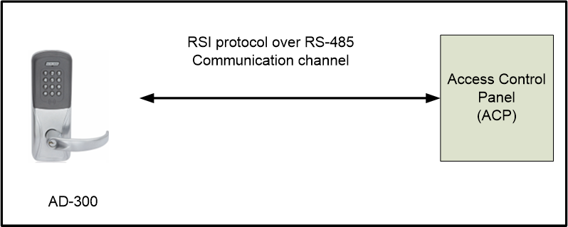
The AD-300 lock is the wired lock in the Allegion AD-series product line and is connected to an ACP using a two-wire or four-wire RS-485 interface.
The AD-series RSI protocol specification document describes the following:
All the commands that can be communicated between the ACP and the networked devices that have an RS-485 connection. The AD-300 and the PIM-400-485 are two products that support the RS-485 communication channel.
Explanation of each command and response and definition of each bit in the command and response is provided in detail.
The packet format and communication rate. For example, all valid packets have a fixed start byte (0x0A) and a CRC/checksum that is calculated in a specific way.
The AD-series RSI protocol runs on a two-wire, half-duplex or four-wire full-duplex bus. There can be up to 32 devices on the bus depending on the ACP capacity. The RS-485 wiring can communicate up to 4,000 feet. Due to physical limitations of the RS-485 protocol, only one node can transmit on the bus at a time. This means that the bus is a master-slave system and all messages are originated by the master. The ACP is always the master and the system is completely controlled by the ACP (address 0xFF) on the bus. The slave nodes (RSDs/APMs) can only respond individually to the commands that have been sent by the master nodes to the individual slave nodes.
It is important to understand that the master node (ACP) sends the appropriate commands to the slave nodes (RSDs/APMs) to accomplish what is necessary for a reliable Access Control solution.
The AD-300 networked wired lock can be connected to the ACP in two configurations, but this document covers the method described in Figure 3-1. This is the direct connection of the AD-300 lock with the ACP since the RSI protocol is used for the communication between the ACP and the AD-300.
The AD-400 wireless networked lock communicates with the PIM-400-485 via the RF channel, which operates in the 902-928 MHz spectrum. The RF protocol used is proprietary to Allegion. See Figure 4-1, below.
The PIM-400-485 is connected to the ACP via the RS-485 bus, and the RSI protocol is used for this communication and does the following:
The PIM-400-485 receives commands from the ACP and forwards them to the AD-400. The PIM-400-485 is the slave device (since the ACP is always the master), and only responds to the ACP when a valid command is sent by the ACP. It is important that the ACP polls the PIM-400-485 device continuously. The faster the ACP polls the PIM-400-485, the quicker it is for a user’s credential to be processed at the AD-400 lock.
A later section covering the Wake-on-Radio (WoR) contains detailed information regarding the polling interval that ACP vendors must use to work with the AD-series of networked devices.
The PIM-400-485 also acts as a slave device in the AD-400/PIM-400-485 RF communication. Whenever the AD-400 has valid data, the lock sends the data immediately to the PIM-400-485 and waits for a valid response from the ACP. The PIM-400-485 stores these messages from several AD-400 devices and forwards them to the ACP whenever there is a poll command.
NOTE: The AD-400 is used as an example in the diagram below and many other times but all information in this document is applicable to any AD-Series wireless device.
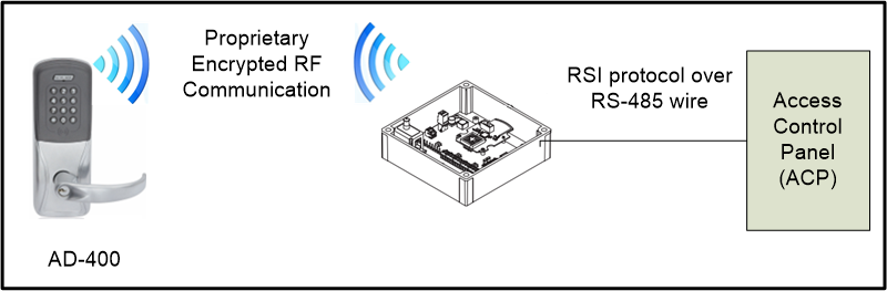
Figure 4-2, shows the communication between the PIM-400-485 and the ACP. The ACP is always the master on the RS-485 bus. This means the ACP ALWAYS initiates communication with the PIM-400-485. The implication is that even though the PIM-400-485 may have received a packet from an AD-Series wireless device, this information remains with the PIM-400-485 until there is a POLL message from the ACP requesting the information from the AD-Series wireless device.
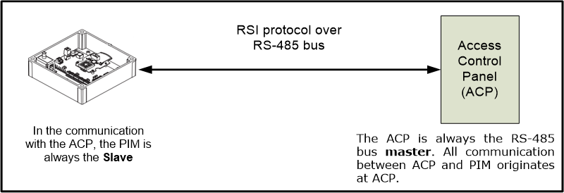
Figure 4-3 shows the communication between the AD-Series wireless device and the PIM-400-485, the AD-Series wireless device is the master. This means that the AD-Series wireless device ALWAYS initiates communication with the PIM-400-485.
When there is any reportable event that happens at the AD-Series wireless device, the lock sends the event via the RF channel to the PIM-400-485. The exception to this is when there is data transfer over the Wake-on-Radio (WoR). The WoR operation is described in a later section of this document.

There are two types of devices which are addressable with the RSI protocol:
APM (Access Point Module) … such as an AD-400 lock
RSD (RS-485 Device) … such as a PIM-485-RSI
There are also two types of commands provided by the RSI protocol that correspond to the two types of devices. APM Commands are used to communicate with APM devices, and RSD commands are used to communicate with RSD devices.
The APM commands and the RSD commands do not have any common message types and therefore any command which is present on the RS-485 bus can be identified by its message type as an APM command or an RSD command.
Most APM commands have APM_ as part of their command name. Two examples are:
APM_LOCK_CONTROL
APM_TIMED_UNLOCK
Most RSD commands have RSD_ as part of their command name. Two examples are:
GET_RSD_MANUFACTURE_DATES
GET_RSD_INFORMATION
NOTES: Due to the fact that the RSI Protocol can address both wired and wireless devices, the following points are noted:
RSI Protocol requires unique RS485 APM addresses for all APM devices on any single ACP RS485 Port.
Even though wireless APM devices do not physically attach to the RS485 bus they still require unique RS485 APM addresses.
RSI Protocol requires unique RS485 RSD addresses for all RSD devices on any single ACP RS485 Port.
A PIM-485-RSI (RSD device) can manage up tp 16 RS485 APM addresses. Each RS485 APM address corresponds to a wireless device (such as an AD-400 lock). A range of RS485 APM addresses is created by setting the LOW ADDRESS and HIGH ADDRESS parameters on the PIM400 (set either via SUS program on a Hand-Held Device or via RSI Protocol by ACP).
This section describes the rules that ACP vendors use to assign addresses to the Allegion series of networked devices.
Rule 1: Each APM is given a unique address within the valid range of APM addresses from 0 to 254.
Rule 2: From the perspective of a single RS485 bus, each APM is a unique device - irrespective of which PIM-400-485 to which the APM is connected. Even across multiple PIM-400s, each APM has a unique address on any given RS485 bus.
Rule 3: There can be no duplicate APM address on any single RS485 bus. There can be duplicate addresses on two different RS485 lines.
Rule 4: Each RSD is given a unique address within the valid range of RSD addresses from 0 to 254. There are two reserved values:
“0xFF” (255) is reserved for the RS485 master (the ACP), and should not be used for any APM or RSD.
“0xAA” (170) is reserved for the broadcast address and should not be used for any APM or RSD.
This section describes a few examples to help setup the Access Control System using Allegion components.
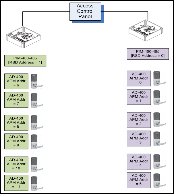
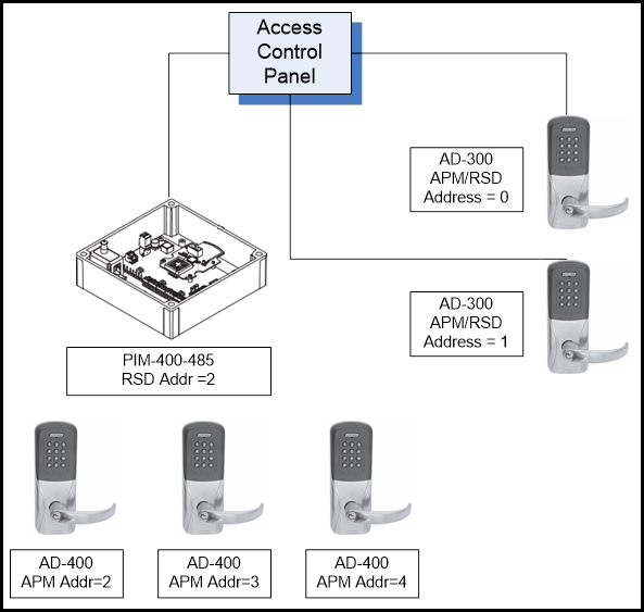
In this example, shown in Figure 5-1, there are two PIM-400-485 devices connected to the ACP. Referring to Rules 5 and 6, it is understood that each PIM-400 is an RSD, and is given a unique address. The following addresses are assigned:
The first PIM-400-485 is assigned address 0.
The second PIM-400-485 is assigned address 1.
Connect (6) AD-400 devices to each PIM-400. Referring to Rules 1-4, the following addresses are assigned:
The first AD-400 connected to the PIM-400 with RSD address 0 is assigned APM address 0.
The next five AD-400 devices connected to the first PIM-400 are assigned address 1-5.
The (6) AD-400 devices connected to the second PIM-400 (RSD address 1) is assigned an APM address of 6, since the address range 0-5 is already taken up by the first set of devices connected to the first PIM-400.
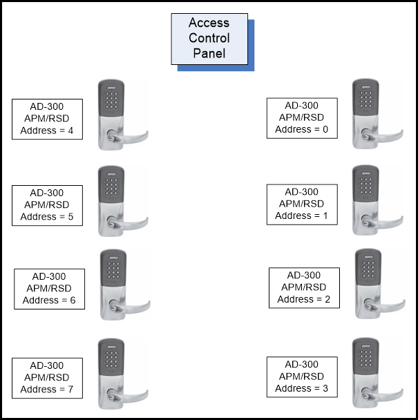
The example shown in Figure 5-2, describes how to setup AD-300 devices and illustrates (8) AD-300 devices connected to the ACP. An AD-300 is both an APM and an RSD device. This should be kept in mind during the addressing setup.
The Wake-on-Radio is a procedure to enable a battery powered AD-Series wireless device to receive an immediate command from the Access Control Panel that is out of sequence with the regular “heartbeat” schedule. Typically, this is a lock or unlock command from the ACP to the device.
In general, a battery powered AD-Series wireless device communicates with the Access Control Panel through the PIM-400 at a regular frequency set by the “Heart beat interval”, which has a factory default setting of 10 minutes to check for any message from the ACP.
Therefore, each battery powered AD-Series wireless device:
Wakes up every “heart beat” interval
Sends out a message to the PIM-400 effectively asking “Do you have anything for me?”
Listens for any command/response from the PIM-400
Takes any action based on the command received from the PIM-400
After the action is taken, the device goes “back to sleep” until the next heart beat interval.
WoR allows the battery powered AD-Series wireless device radio to listen for beacons at regular intervals (settable from 1 sec to 10 secs, default is 10 sec). If the ACP enables WoR operation and sends any message to the PIM-400, a battery powered AD-Series wireless device will receive the message within 10 seconds, (compared to the regular 10 minute heart beat interval). The WoR feature enables a battery powered AD-Series wireless device to receive an immediate command such as Lock or Unlock rapidly and allows the Networked System to quickly respond to emergency situations.
It is important to note that when WoR is enabled, there is an impact to battery life as a tradeoff to the enhanced responsiveness. This impact to battery life applies to all devices linked to the respective PIM-400.
The Wake-on-Radio is a special feature of the battery powered AD-Series wireless devices and utilizes battery life and RF communication on the lock differently when it is enabled vs. disabled.
AD-Series wireless devices receive commands more quickly: Normally, the radio in the lock wakes itself up every Heart Beat Interval (default value 10 minutes) and transmits (checks in) to the PIM Radio. It is at this time that the lock can receive any updates from the PIM. When WoR is enabled, a beacon signal is now transmitted by the PIM Radio. The lock Radio wakes itself up every beacon period (default value 10 seconds) and listens for this beacon (note the difference in which radio initiates communication when WoR is enabled vs. disabled). The lock is now able to receive updates at a much quicker time interval (and thus be able to respond in near real-time to urgent commands such as lockdown, etc).
8-10% Reduction in Battery Life: A heartbeat involves both a Transmit and Receive operation on the Radio channel. The lock transmits its current status, and also listens for any message from the PIM-400. This operation typically takes approximately 50-75 milliseconds. With the Wake-on-Radio enabled, the AD-Series wireless device primarily performs a Receive operation on the Radio channel, and the Radio chip is awake for only approximately 4-6 milliseconds. While each event is much shorter in time and power requirement, this event occurs much more frequently. (i.e. 1 Hearbeat vs. 60 WoR in a 10-minute interval) This means an increase of upto 10% extra current This correlates to an estimated 10% reduction of battery life if WoR is enabled with the default setting of 10 seconds.
WoR battery usage does not depend on cycles/day lock usage: It is to be noted that irrespective of the number of cycles the lock is used in the customer’s location (Eg: 20 cycles/day, 50 cycles/day, 100 cycles/day etc), there is a flat battery drain characteristic once the WoR is enabled.
WoR can be enabled in two ways:
The user connects an HHD via the USB cable to the PIM-400 and sets the appropriate parameter to enable the Wake-on-Radio in the “Edit Properties” tab. Please note that this enables WoR for all the locks and Wireless Portable Readers (WPR) connected to the PIM-400.
The ACP sets the WoR for all the devices connected to a specific PIM-400 by using the “SET_RSD_WOR” command. This command also contains the WOR wakeup frequency parameter that determines how often the AD-Series wireless device radio should wake up to listen for messages from the PIM-400.
NOTE: When the WoR feature is enabled by either of the two ways described, all locks and WPRs connected to the PIM-400 have their WoR turned on as well.
NOTE: In option #1 above, the WoR feature is enabled using the SUS at the PIM-400 and not the lock. This feature cannot be enabled at the lock.
Details on how to form the RSI command in the ACP software is provided in the sections below.
There are three commands available for the ACP vendors to work with the Wake-on-Radio feature:
This command is typically used during initialization of the ACP and decides if Wake-on-Radio feature is enabled or disabled by default. It is recommended that default = disabled. The factory default value is disabled.
When an ACP enables the WoR feature, the data bytes are filled appropriately with the wakeup frequency and sent to the PIM-400.
Once the battery powered AD-Series wireless device receives this command from the PIM-400 (ie; during the next heartbeat interval), the WoR feature is enabled, and the battery powered AD-Series wireless device radio starts listening to traffic from the PIM-400 every wakeup interval.
| Byte | Field | Data/Description |
|---|---|---|
| 1 | Start of Frame | 0AH |
| 2 | RSD Address | 00H to FEH and not AAH |
| 3 | Type | 47H |
| 4 | Length | 02H |
| 5 | Data | Sub Command: 07H |
| 6 | WOR: 0-10 seconds; 0=WOR disabled | |
| 7/8 | Frame Check Sequence | CRC or CHECKSUM |
NOTES:
Byte 5 must contain 0x07
Byte 6 contains the frequency of wakeup in seconds. If this byte is set to 0 (Zero), WoR is disabled.
Values from 1-10 set the wakeup time of the AD-Series wireless device lock.
For example, if this value is set to 10, the AD-Series wireless device wakes up every 10 seconds and listens for new commands/messages from the PIM-400 on the Wake-on-Radio channel.
This is used by the ACP when a command is to be sent to the designated battery powered AD-Series wireless device which is connected to the PIM-400. This command alerts all devices linked to the PIM-400, however, it still allows the ability to drive a command to specific devices while allowing others on the same PIM-400 to ignore the command. (i.e. lock down doors 0-4, yet do not change state of doors 5-15). This command has two parameters:
Lock bitmap --> The lock bitmap consists of two bytes - 16 bits, each bit denotes a single device, with the lowest address on bit 0. (Eg: if the devices from 1 through 4 connected to the PIM-400 need to be addressed, the bitmap to be used is 0x0F00). This bitmap determines which devices wake up and take action based on the control bitmap. (Examples shown below).
Control bitmap --> The control bitmap is very similar to the lock bitmap in terms of addressing (LSB bit denotes the lower addressed AD-Series wireless device). A 1 denotes “unlock the door”, and a 0 denotes “Lock the door”. (Eg: if the ACP wants to unlock doors 0-7, the bitmap that must be used is 0xFF00).
| Byte | Field | Data/Description |
|---|---|---|
| 1 | Start of Frame | 0AH |
| 2 | RSD Address | 00H to FEH and not AAH |
| 3 | Type | 47H |
| 4 | Length | 05H |
| 5 | Data | Sub Command: 08H |
| 6 | NOTE: Bit 0 addresses the first lock connected to the PIM-400, and Bit 15 addresses the last lock connected to the PIM-400. | Lock Bit Map Low Byte: Bit0-1st lock on the PIM 1-wakeup this lock, 0-don’t wakeup this lock |
| 7 | Lock Bit Map High Byte: Bit0-9th lock on the PIM 1-wakeup this lock, 0-don’t wakeup this lock | |
| 8 | Control Bit Map Low Byte 1-unlock, 0-relock | |
| 9 | Control Bit Map High Byte 1-unlock, 0-relock | |
| 10/11 | Frame Check Sequence | CRC or CHECKSUM |
Case 1: There are 10 devices connected to a PIM-400 with addresses 1-10. Assume the ACP only wants to address locks 1, 2 and 3 and have these devices move to the UnLocked state.
Set lock bitmap value to 0x0700 and
Control bitmap must be set to 0x0700
Case 2: There are 10 devices connected to a PIM-400, with addresses 1-10. Assume the ACP wants to address all the locks and have these devices move to the Locked state.
Set lock bitmap value to 0xFF03 and
Control bitmap must be set to 0x0000
Case 3: There are 8 devices connected to a PIM-400, with addresses 1-8. Assume the ACP wants to address all the locks and have locks 1-4 move to the Locked state and locks 5-8 to move to the Unlocked state.
Set lock bitmap value to 0xFF00 and
Control bitmap must be set to 0xF000
Case 4: There are 8 devices connected to a PIM-400, with addresses 1-8. Assume the ACP wants to address all the locks and have locks 1-4 move to the UnLocked state and locks 5-8 to move to the Locked state.
Set lock bitmap value to 0xFF00 and
Control bitmap must be set to 0x0F00
This command is used by the ACP to find out if the PIM-400 has done the following:
Sent the SET_WOR_WAKEUP command to the AD-Series wireless device
See if the AD-Series wireless device has responded to the SET_WOR_WAKEUP command
Depending on the Radio protocol used, it may take from 2-10 seconds for any specific AD-Series wireless device to respond to the SET_WOR_WAKEUP command. See Table 6-2 above, for details of the command. It is important that once a SET_WOR_WAKEUP command is sent, that affects any particular AD Series Lock, that no additional SET_WOR_WAKEUP commands are sent to that affected lock until the ACP is able to confirm that the initial command has completed for that lock.
| Byte | Field | Data/Description |
|---|---|---|
| 1 | Start of Frame | 0AH |
| 2 | RSD Address | 00H to FEH and not AAH |
| 3 | Type | 47H |
| 4 | Length | 01H |
| 5 | Data | Sub Command: 09H |
| 6/7 | Frame Check Sequence | CRC or CHECKSUM |
The PIM responds to this command and sets the appropriate value in bytes 6, 7 and 8. If all the locks connected to the PIM-400 have already been awakened, the appropriate bits in the 7th and 8th byte are set. See Table 6-4 below for details.
| Byte | Field | Data/Description |
|---|---|---|
| 1 | Start of Frame | 0AH |
| 2 | RSD Address | 00H to FEH and not AAH |
| 3 | Type | 36H |
| 4 | Length | 04H |
| 5 | Data | Sub Command: 89H |
| 6 | Command Execution Status: Bit0: 0-in process, 1-completed | |
| 7 | Lock Bit Map Low Byte: 0 – Lock woke up; 1 – Lock NOT woke up | |
| 8 | Lock Bit Map High Byte: 0 – Lock woke up; 1 – Lock NOT woke up | |
| 9/10 | Frame Check Sequence | CRC or CHECKSUM |
NOTE: Another way to get the WOR processing status is to send SET_WOR_COMMAND with extended status enable. With extended status enable, PIM reports WOR status to the ACP in response to polling command (refer to Section 6.5.4). There is no need to send GET_WOR_STATUS separately to get the WOR processing status.
The following (5) scenarios to follow represent the most common use cases for Wake-on-Radio.
ACP Enables Wake-on-Radio
ACP Disables Wake-on-Radio
ACP Sends Lock/Unlock Command to Designated Devices Connected to the PIM-400
ACP Sends Lock/Unlock Command to Designated Devices Connected to the PIM-400 (With Extended Status Enabled)
ACP Sends Multiple Lock/Unlock Commands to Designated Devices Connected to the PIM-400 Within the Same WoR Time Frame
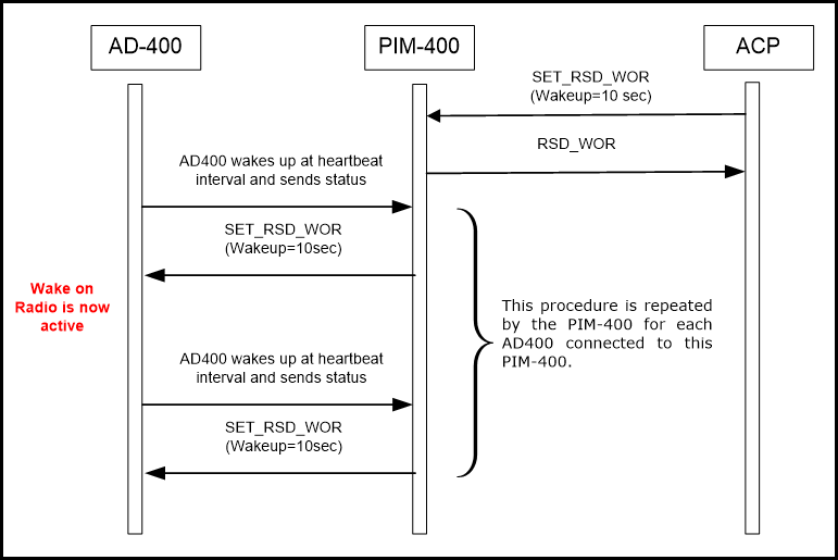
To enable the Wake-on-Radio, the ACP sends SET_RSD_WOR (wakeup = value). It is strongly recommended not using the wakeup frequency of less than the default value of 10 seconds. Read the section Impact of Enabling WoR to fully understand the implications of enabling WoR.
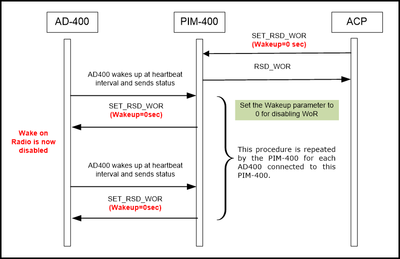
To disable the Wake-on-Radio that was previously enabled, the ACP uses the same command SET_RSD_WOR, but the wakeup value is set to Zero (0).
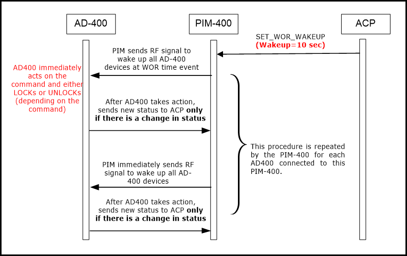
The primary purpose of enabling the Wake-on-Radio is to ensure the AD-Series wireless device can respond to emergency situations within a very short duration of time (within a few seconds).
The ACP uses the SET_WOR_WAKEUP with the appropriate bitmap to either wakeup or ignore designated devices connected to a particular PIM-400 and then drive a lock or unlock command.
NOTES:
A specific set of doors to be controlled is selected using the lock bitmap.
The eventual state the AD-Series wireless device must move to (locked state or unlocked state) is selected using the control bitmap.
The AD-Series wireless device sends a status change message only if the new status is different than the current status. Example: if the lock was already in the Locked state, and the SET_WOR_WAKEUP command is used to set the AD-Series wireless device in Locked state, a status message is NOT sent.
If the new state is different than the previous state of the AD-Series wireless device (either Locked to Unlocked, or vice versa), a status message is generated from the AD-Series wireless device, which then gets forwarded to the ACP via the PIM-400.
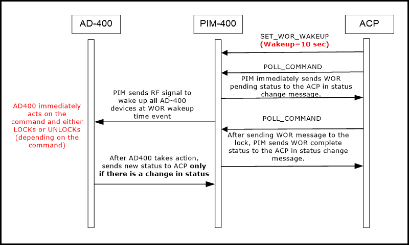
In this case, the lock behaves as the previous case but PIM responds to the ACP with WOR status in extended status change response. This feature enables ACP to track WOR processing status without sending GET_WOR_WAKEUP_STATUS command.
After receiving WOR wakeup command from the ACP, PIM responds with the WOR pending status. Once PIM sends Wakeup command (after WOR timeout) to the AD-400, PIM responds with the WOR completed status in STATUS_CHANGE_EXTENDED response.
NOTES:
PIM does not wait for the successful execution of the command on the AD-400. PIM only ensures that the wakeup command is successfully sent to the AD-400.
When WOR feature is disabled, after receiving WOR wakeup command, PIM does not report WOR pending staus.
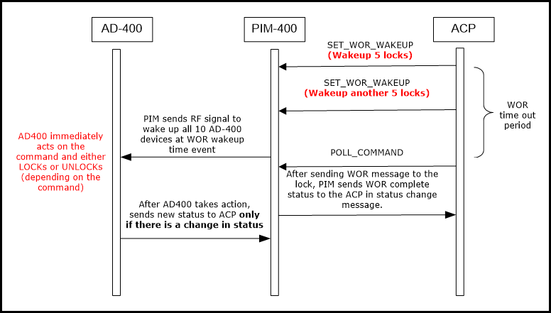
In this case PIM handles all subsequent WOR wakeup commands sent by ACP within the same WOR time frame. If ACP sends multiple WOR wakeup commands to the PIM within the same WOR time frame, PIM handles all the commands and wakes up all the requested locks on the WOR time event.
Example: When ACP sends WOR wakeup command to any 5 locks linked with PIM and before WOR time event (consider 10 sec), if ACP again sends WOR wakeup command to another 5 locks, on WOR time event, PIM wakes up all the locks requested from the first and second commands.
Use case described with RSI messages:
Enable WOR.
Send SET_WOR_WAKEUP to first lock on the PIM. (0A 00 47 05 08 01 00 01 00)
On next polling by ACP, PIM will respond with RSD_STATUS_CHANGE_EXTENDED (0A FF 34 08 00 01 20 15 01 00 01 00) in which 8th byte indicates WOR status pending.
Send SET_WOR_WAKEUP to second lock on the PIM quickly, before WOR time event. (0A 00 47 05 08 02 00 02 00)
Send GET_WOR_WAKEUP_STATUS command to get the complete bitmap of wake-up locks. The following status is observed:
Data Byte 2 - Command Execution Status: 00 (WOR Pending)
Data Byte 3 - Lock Bit Map Low Byte: 03
Data Byte 4 - Lock Bit Map High Byte: 00
After WOR is sent to both the locks, the PIM will respond with RSD_STATUS_CHANGE_EXTENDED (0A FF 34 08 00 01 20 15 01 00 01 08) in which 8th byte indicates WOR status completed.
Send GET_WOR_WAKEUP_STATUS command to get the complete bitmap of wake-up locks. The following status is observed:
Data Byte 2 - Command Execution Status: 01 (WOR executed)
Data Byte 3 - Lock Bit Map Low Byte: 00
Data Byte 4 - Lock Bit Map High Byte: 00
The RSI Protocol only supports the polling mode of operation – meaning that the bus master ALWAYS initiates communication. This behavior of Allegion networked locks has important implications for Access Control Panel vendors.
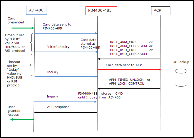
When a credential (card or PIN or card + PIN) is presented to the AD-Series wireless device, the AD-Series wireless device immediately sends the data via RF to the PIM-400-485. The PIM-400-485 “buffers” this data until it receives a POLL command (or any other command) from the ACP.
After the AD-Series wireless device sends the credential information to the PIM-400-485, the lock sends an “Inquiry” command to the PIM-400-485 essentially asking the question “Have you received any response from the ACP”? This Inquiry time (time between the AD-Series wireless device sending the credential information and following it up by an Inquiry) is a parameter that is set by the SUS or the AD-series RSI protocol. The default Inquiry time is 300ms. The “retry” parameter allows the user to choose the number of attempts the AD-Series wireless device makes to send the data to the PIM-400-485 - the default is (3) attemps.
The ACP sends the APM_POLL command to the PIM-400-485. The PIM-400-485 then proceeds to forward the previously received credential data to the ACP.
The ACP performs an internal lookup from its database to verify if the credential shown is valid and sends the corresponding command back to the PIM-400-485.
The PIM-400-485 now holds the response from the ACP in its buffer until it receives the next “Inquiry” command from the AD-Series wireless device. As a response to the Inquiry command, the PIM-400-485 sends the ACP’s reply to the original credential information sent by the AD-Series wireless device. This completes one credential read cycle.
A device on the RS-485 bus (RSD/APM) must answer with exactly one message if the request message (command) was addressed to that device. There is no published time that the RSD has to respond to the poll message before the message is resent or another message is sent to that RSD or another RSD. The maximum time for this response should be less than 150-200ms before the ACP can assume that the RSD/APM will not respond and the bus is free to send another command.
The AD-300 and AD-400 devices work well in an environment when the Polling interval from the ACP follows the guidelines provided in Table 7-1 below:
| Polling Interval | Recommendation |
|---|---|
| Less than 500ms | Strongly recommended. Devices work best in such an environment. Feedback to the user is almost instantenous. |
| 500 ms – 750 ms | If polling at rates < 500 ms is not possible, this is the next best frequency. At this polling rate, the feedback to the user will start to slow down, and users may begin to notice a slight “delay” in response times. |
| 750ms – 1000 ms | System works, but at this frequency, there will be noticeable delays for a user as it approaches 1 sec |
| Greater than 1000ms | NOT recommended. AD-300 and AD-400 are not designed to work beyond this range, and operations are not guaranteed |
Polling the devices is a crucial parameter that is considered in the design and deployment of the Access Control System.
To better educate ACP vendors, the sections below give examples of the message flow between the various system blocks. The various message flows provide insight into the internal workings of the Access Control System.
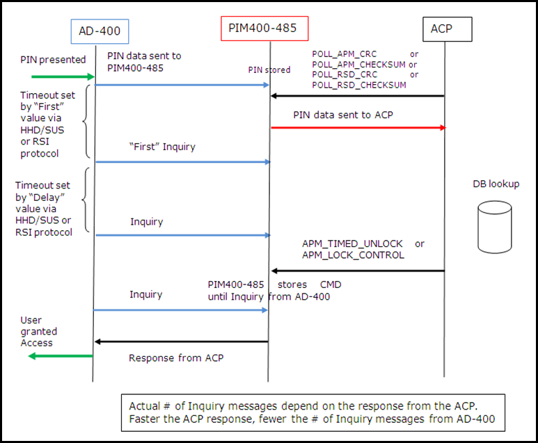
This section describes the message flow for a Valid CARD only credential.
NOTES: The actual number of “inquiry” messages sent from the AD-Series wireless device depends on several factors:
“First” parameter value: This can be set via the HHD/SUS or RSI protocol. The default value is 300 ms, and this can be varied depending on the actual response time from the ACP. We recommend users set this variable based on the polling frequency from the ACP. The lower the "Subsequent delay" parameter value the better, as this correlates to fewer inquiry messages and longer battery life for the AD-Series wireless device.
ACP Response Time: the faster the frequency of APM_POLL messages, the quicker the response from the AD-Series wireless device, and the overall response time for the user will be better.
ACP Database lookup time: The time it takes to perform a database lookup at the ACP – the longer it takes to do the lookup, the more inquiry messages will result.
Timeout due to lack of response from ACP: If the AD-Series wireless device does not receive any valid response from the ACP after the designated "Retry" quantity of Inquiry messages, (default set to 5), it assumes the entered credential is invalid, and displays the “Invalid credential” LED pattern on the device.
We recommend tuning these parameters depending on actual system response times during the installation.
The message flow for a Valid Card presentation is shown below in Figure 7-1.
This sequence is identical to that of the CARD only, with the only difference being that PIN data is transmitted to the ACP instead of card data.
NOTE: Depending on the specific keypad format chosen (Byte 19 of the NEXT_GEN_APM_CONFIGURATION command), the AD-Series wireless device sends the PIN data to the PIM-400-485.
In buffered mode, all bytes are sent in one packet
In all other modes, each individual PIN character is sent as a separate packet.
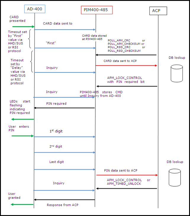
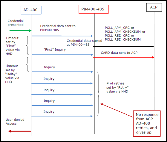
NOTE: This figure applies to all credential sequences (Card, Pin, or Card + Pin).
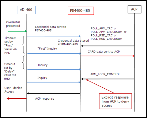
NOTE: This figure applies to all credential sequences (Card, Pin, or Card + Pin).
By now, looking at the sequence diagrams it may be apparent that the polling time significantly impacts the amount of message traffic from the AD-Series wireless device.
Since the AD-Series wireless device is likely battery operated, we recommend the following values for these parameters to get a better battery life and also have quicker response to the user when a credential is shown at the lock.
| HHD/SUS/RSI Protocol Parameter | Value |
|---|---|
| First | 300ms |
| Delay | 200ms |
| Retry (# of retries) | 5 |
Over-the-Network Reflash (ONR) refers to the capability of a networked device to have its application firmware reprogrammed by the ACP. This eliminates the need to travel to each door with an SUS to upgrade the firmware which saves the customer both time and money.
In general, there are two main phases of the ONR process. The first is for the ACP to download the file (or files) to the networked devices. During this download the networked device stores the firmware file in eeprom for later use. Once the download is complete the ACP performs the second phase of instructing each networked device to go ahead and reprogram itself using the file that was downloaded.
This process is separated into two steps because this allows the networked devices to remain online for the maximum amount of time as well as allowing the ACP to more precisely schedule the time when the networked devices are offline. The download happens in the background with minimal impact to normal functionality and only after receiving the command to start reprogramming does the networked device fall offline. It resumes communication once the reprogramming is complete and the new application has started.
With this feature the ACP can reprogram the following AD devices:
AD-300 main board
AD-400 main board (must be linked to PIM400-485)
AD reader (must be attached to AD-300/AD-400)
PIM400-485 (includes both RSI and VBB types)
This feature does not allow for the reclassing of a device. For example, the AD-300 only accepts AD-300 firmware. Since reclassing requires the user to perform some steps at the lock anyway there is not a big disadvantage to the customer in not accommodating this functionality, and this could potentially prevent accidental reclassing from occurring.
There are a few prerequisite setup steps that must be completed prior to starting the ONR process. The first step is to verify that the current version of installed firmware that is in all of the networked devices supports the ONR feature. One method to do this is to use the GET_FULL_FIRMWARE_VERSION message to obtain the firmware version installed in the AD-300, PIM400-485 and/or AD-400. This message only provides the FW version of the main board on the locks. To fetch the reader firmware versions, use the msg GET_READER_INFO. Even if the user wants to use ONR to update the firmware only on the main board, the reader must still be compatible with ONR. The following are the minimum required versions that must be installed:
AD-300 main board: 2.43.2
AD-400 main board: 2.43.2
KP/PR(K)/SM(K)/MT(K)/Mi(K): 2.42.1
MG(K)/MS(K): 2.40.1
PIM400-485-RSI: 2.23.1
PIM400-485-VBB:2.23.1
NOTE: The MTK2 platform of readers (KP2/MT2/MTK2/Si2/SiK2/FMK2) was introduced after the initial release of the ONR feature. As such, all versions of these readers support ONR. However, to ensure proper operation with the AD main boards the AD-300 and AD-400 must be at or above a certain firmware version threshold. Here are the minimum versions of firmware that should be installed in the case that an MTK2 platform of reader is installed before ONR should be attempted.
AD-300 main board: 2.47.2
AD-400 main board: 2.47.2
KP2/MT2/MTK2/Si2/SiK2/FMK2: 2.1.4
PIM400-485-RSI: 2.27.2
PIM400-485-VBB:2.27.2
If the device does not have a version of firmware greater than or equal to the listed versions then the networked device must be updated manually to a compatible version using the SUS before the ONR feature can be used.
The Wake-on-Radio feature is an integral part of the AD-400 ONR process. To use the ONR feature for the AD-400 devices WoR must be enabled. The recommended WoR interval setting is 10 seconds for using the ONR feature. For more information on WoR and how to enable see the corresponding section in this document.
NOTE: If the ACP enables WoR just prior to performing an ONR, it will take time for the WoR setting to be enabled in all target devices. This is because the PIM must wait for the next communication from the AD-400 before it can instruct the AD-400 to enable WoR. For this reason, the WoR setting should not be adjusted once the ONR process has begun.
The ONR firmware files can be retrieved from the same place on the internet where the SUS package files are currently obtained. They will be part of the zip file for every firmware release from AD.A.60 moving forward. They will be clearly labeled in an ONR folder within this zip drive.
The ACP should send the entire unzipped hex file as received from the web in the downloaded zip file as described in the previous section. There is no need for the ACP to do any special handling of the data prior to sending it to the device. There is an individual ONR file for each product type. These ONR specific files are separate from the SUS package file that is used to upgrade firmware using the SUS. Whether programming a device using the SUS or using the ONR feature, the resulting FW image in the target device will be identical. It is the ACP’s responsibility to ensure that the devices are all updated with compatible firmware versions from the same packaged release. Table 8-1 lists the ONR file names for each of the products that support ONR.
| Product Type | Model Number* | ONR Hex Filename (xx.xx.xx refers to version) |
|---|---|---|
| AD-400 main board | “AD-400” or “AD401” | ONR_AD-400_xx.xx.xx.hex |
| AD-300 main board | “AD-300” or “AD301” | ONR_AD-300_xx.xx.xx.hex |
| Keypad Only Reader | 19=RDR-KP | ONR_KP-PR-SM-MT_xx.xx.xx.hex |
| Prox Reader | 23=RDR_PROX_NO_KPD | |
| Prox + Keypad Reader | 0=RDR-PROX | |
| Smart Reader | 22=RDR_SMART_NO_KPD | |
| Smart + Keypad Reader | 2=RDR-SMART | |
| Multi-Tech Reader | 21=RDR_MT_NO_KPD | |
| Multi-Tech + Keypad Reader | 18=RDR-MT | |
| Multi-Tech + iClass Reader | 31=RDR_Mi_NO_KPD | |
| Multi-Tech + iClass + Keypad Reader | 32=RDR_Mi_WITH_KPD | |
| FIPS Multi-Tech + Keypad Reader | 17= RDR-FMK(FIPS) | |
| Mag Insert Reader | 20=RDR_MAG_NO_KPD | ONR_MG_xx.xx.xx.hex |
| Mag Insert + Keypad Reader | 1=RDR-MAG | |
| Mag Swipe Reader | 25=RDR_MAGSW_NO_KPD | |
| Mag Swipe + Keypad Reader | 16= RDR_MAGSW_KPD | |
| Keypad 2 Reader | 60=RDR_KP2 | ONR_KP-PR-SM-MT2_xx.xx.xx.hex |
| Mutli-Tech 2 Reader | 62=RDR_MT2_NO_KPD | |
| Multi-Tech + Keypad 2 Reader | 61=RDR_MT2_WITH_KPD | |
| Smart iClass 2 Reader | 59=RDR_Si2_NO_KPD | |
| Smart iClass + Keypad 2 Reader | 58=RDR_Si2_WITH_KPD | |
| FIPS + Keypad 2 Reader | 65=RDR_FM2_WITH_KPD | |
| PIM400-485-RSI | “PIM400” | ONR_PIM400-485-RSI_xx.xx.xx.hex |
| PIM400-485-VBB | “PIM400” | ONR_PIM400-485-VBB_xx.xx.xx.hex |
*Model number for readers is as reported through the RSI protocol through the READER_INFORMATION response. The Model number for the main board/PIMs is as reported through the AD_APM_OEM_CODE and AD_RSD_OEM_CODE responses.
The ACP is responsible for initiating a new ONR firmware download session. This can be done by using the START_FW_DOWNLOAD message that is defined in the RSI Protocol. In this message the ACP must provide the intended target of the ONR download. This means that the ACP must be aware of what product types/reader types are currently installed at each APM/RSD address. This can be done using the GET_AD_RSD_OEM_CODE, GET_AD_APM_OEM_CODE, and GET_READER_INFO messages defined in the RSI Protocol.
An ONR download session as it is used in this document is defined as a single download for the AD-300, PIM400-485, or one or more AD-400s linked to a single PIM400-485. Using this terminology, it takes multiple ONR download sessions to fully upgrade all devices on a single RS485 bus.
If the target is an AD-300 or a reader attached to an AD-300 then the lock bit map bytes should be set to 0x00. If the target is the PIM400-485 the lock bit map bytes should also be set to 0x00. If the target is a set of AD-400s or readers attached to AD-400s then the bitmap should be used to indicate which AD-400s linked to the PIM are targeted for the download. This bitmap is setup in a similar manner to how the bitmap for the WoR related commands is defined, with the lowest APM address being controlled by bit 0 of the first bitmap byte.
When this message is received by the target device it confirms that the target type listed in the message is valid for the hardware/firmware that is currently installed at the target address. This is to prevent reclassing of devices or the installation of improper firmware for the given hardware.
The target device also performs a verification to ensure that the setup requirements have all been met as described in the Device Requirements to Support ONR section of this document.
For battery operated devices (AD-400) there is a check to ensure that the lock is not currently in a low battery state. The ONR download process is not allowed to start while the lock is in such a state. The user needs to replace the batteries if this is the case prior to starting the ONR process.
NOTE: A single RSD device can only support one ONR download session at a time. This means that the reader and the main board applications must be downloaded one at a time and cannot be done in parallel. Also, the PIM application cannot be downloaded in parallel while downloading the FW to the AD-400s linked to that PIM.
This means that AD-400s cannot be added to an already active ONR download session for a set of AD-400s. For example; if an ONR download session is active for doors 0-3 linked to a single PIM and the ACP sends a START_FW_DOWNLOAD message for AD-400s 4-7 linked to the same PIM, then the previous session for doors 0-3 will be aborted and the new session for doors 4-7 will start.
If the desire is to have all eight doors (0-7) be part of the same download session, then a single START_FW_DOWNLOAD message with the appropriate bitmap should be sent.
However, the ACP may have multiple ONR download sessions active at the same time as long as there is not more than one active session per RSD address. For example; if there are 10 AD-300s on an RS485 bus, the ACP can download files to these locks in parallel. The burden in this scenario is on the ACP to manage multiple downloads because broadcasting of messages on the RS485 bus is not supported for this feature.
The ACP must duplicate all ONR messages for each RSD address, even when downloading the same FW file to each device. It is the ACP’s responsibility to balance the throughput of the ONR download and the round-robin polling time in order to ensure that credentials are granted access within a timely manner even when multiple ONR download sessions are active. There are no timeouts associated with the ONR download, so the ACP may take as much or as little time between downloading consecutive blocks of the firmware file as required. For this reason, handling the polling commands/responses should always take priority over anything related to ONR.
If the request to start a new ONR download session is accepted, then the START_FW_DOWNLOAD_RESP indicates that no error was found with the request (response code 0x00). If the START_FW_DOWNLOAD_RESP message indicates that the processing of the message is In-Progress (response code 0x01) then the ACP needs to poll the ONR Status until either an error or acceptance of the start download request occurs. See later sections for methods to retrieve ONR status and details on the error response codes.
Once the download session starts, the ONR firmware file can be sent 64 bytes at a time using the FW_FILE_BLOCK message as defined in the RSI Protocol. In this message the ACP provides the block ID associated with the data that is being downloaded. This block ID value should start at 0x0001 for the first block of data and be incremented by one for each additional block of data that is sent for the download.
If the block of data is accepted, the FW_FILE_BLOCK_RESP message indicates that no error was found (response code 0x00). If this is the case, then it is safe for the ACP to proceed with sending the next block of data.
If further processing is needed, the FW_FILE_BLOCK_RESP message indicates that the block of data is In-Progress (response code 0x01). If this is the case, then the ACP should poll for the ONR Status until either an error or acceptance is indicated in the status. The ACP should not send anymore FW file data until acceptance of the current FW file block is indicated.
If the block of data was rejected, then the FW_FILE_BLOCK_RESP message indicates the appropriate error code. For more details on the error response codes see later sections.
For the AD-400 download case the PIM buffers 1024 (16 FW file blocks) bytes of data before downloading the information to the targeted AD-400s. It takes the PIM approximately 8-9 seconds (best case) to download the entire buffer to a single AD-400. If multiple AD-400s are in the download then the PIM downloads the entire buffer to each lock one at a time, so the amount of time for the PIM to process the entire buffer linearly increases for each additional AD-400 in the download.
The PIM has two of these FW file data buffers so that while it is downloading data to the AD-400s it can still receive more data from the ACP. It is only when both buffers are full that the ACP receives the In-Progress (response code 0x01) notification.
To download the data as fast as the PIM allows, the ACP should be able to provide 1024 bytes of data at a quicker rate than the PIM is able to download the same amount of data to each of the targeted AD-400s. This way when the PIM is finished with one buffer the other is already ready for processing.
Once the ACP has downloaded the entire ONR FW file, it should indicate that the file is complete by sending the END_FW_DOWNLOAD message as defined in the RSI Protocol. Upon receipt of this message the target device verifies the integrity of the stored FW image.
If the END_FW_DOWNLOAD message is accepted, the validation process that initiated the END_FW_DOWNLOAD_RESP message indicates that it is In-Progress (response code 0x01). The ACP then proceeds to poll for the ONR Status until either an error or success indication comes in the status.
After the file validation process has succeeded the ACP can command the device to reflash the downloaded file by using the START_FW_REFLASH message as defined in the RSI Protocol. The ACP can elect to do this step immediately or wait and do it at anytime in the future; such as at a time of least disruption to end users. The FW image is stored in the target devices and ready for reflash until the devices are commanded to reflash via ONR, commanded to ONR Abort, or are FDRed. Similar to the START_FW_DOWNLOAD message, the ACP provides the target type and bitmap in this message.
If the START_FW_REFLASH request is accepted, then the START_FW_REFLASH_RESP message indicates that the reflash process is In-Progress (response code 0x01). Prior to reflashing, the FW image stored is revalidated to ensure nothing has changed since the original download. The target device falls offline for 1-2 minutes while the downloaded application file or files are reflashed. When the device comes back online and reflashing succeeded, the ONR status indicates that the device is ready to start a new download session. The ACP can verify that the application version is correct by using the GET_FULL_FW_VERSION and GET_READER_INFO commands defined in the RSI Protocol.
As previously mentioned the AD devices can only support a single ONR download session at a time. However, it does allow the ACP to download multiple file types sequentially prior to issuing the request to reflash. The files can be downloaded in any order, but the key point is that these downloads are done sequentially and not in parallel.
For example, the ACP can first download the AD-400 main application, then the AD-400 reader application, and finally the PIM400-485-RSI application. It can then instruct the AD-400 to reflash and it reflashes both the reader and the main. After the reflashing of the AD-400 is successful, the ACP then issues a command to reflash the PIM400-485-RSI and it reflashes itself.
To ensure compatibility between the reader, main board and PIM it is strongly recommended that the ACP always download all the updated applications from a given packaged release prior to performing any reflashing. For similar reasons it is also recommended that all of the AD-400s linked to a single PIM are updated with the same version of firmware at the same time by first downloading the application to all of the locks and then issuing a single START_FW_REFLASH command to reflash all of the AD-400s linked to that PIM. It is also recommended that the AD-400s always be reflashed prior to reflashing the PIM as a reflash of the PIM causes a reset in the PIM which then requires the PIM to re-synchronize with the AD-400s prior to being able to reflash those devices.
If for any reason during the ONR process the ACP wants to restore a target device to its default ONR idle state, then the ACP should send the ABORT_FW_DOWNLOAD message as defined in the RSI Protocol. The ACP has to include the target bitmap similar to what is described for the START_FW_DOWNLOAD message. In this way the ACP selectively chooses which devices to abort.
To abort the AD-300/PIM400-485-RSI the target bitmap must be sent as 0x0000. To abort the AD-400 the target bitmap must be used to choose which of the linked devices should be aborted. If only a subset of the AD-400 devices in an active ONR download are aborted, then the download can continue with the remaining devices that were not aborted. This could become useful should an error occur with a single AD-400 in a download because rather than having to abort the entire download, the single AD-400 with the error can be aborted and the download continued with the rest of the devices.
When the abort request is processed by the device it indicates that the message was accepted by sending the ABORT_FW_DOWNLOAD_RESP with the no error response (response code 0x00). When the device accepts the request, it deletes any previously downloaded files and returns to the not active ONR state. For example, if the reader application has been downloaded and then during the download session for the main application there is a request to abort, both the reader application and the partial main application are deleted.
If the abort request cannot be accepted for some reason the appropriate error response code is sent in the ABORT_FW_DOWNLOAD_RESP message. For more details on possible error response codes refer to later sections.
There are two different ways the ACP can poll the status of the ONR process. This can be done by using the GET_ONR_STATUS message or by using the extended APM/RSD status reporting feature of the AD devices.
Sending the GET_ONR_STATUS message results in receiving the ONR_STATUS message which provides a full description on the current ONR state. This response has three main pieces of information: Status Identifier, Status Code, and Status Bitmap.
The Status Identifier and Status Code are used to determine what the current state of the ONR process an RSD device is in. If the Status Code indicates “Ready”, then the Status Identifier represents the next expected message in the typical ONR process. This does not mean that the message indicated is the only one that could be accepted, but the focus is on the typical use case. If the Status Code indicates “In-Progress” or any of the error codes, then the Status Identifier represents the message that is being processed or was the cause of the error.
The Status Bitmap is used to indicate which devices the status applies to and is only used for the AD-400 ONR process. If the current ONR process is for the AD-300/PIM, then the status bitmap is 0x0000.
Table 8-2 goes over the meaning of the ONR status combinations. This section only covers the typical use cases for the “Ready” and “In-Progress” status codes. For more details on the error status codes see later sections.
| Status Identifier | Status Code | Meaning | Next ACP ONR Action |
|---|---|---|---|
| 0x00 – Start FW Download | 0x00 – Ready | The ONR process is idle and no file has been downloaded or is ready to be reflashed. This is the status after performing an FDR or after all downloaded files have been reflashed successfully. | Start a new ONR download |
| 0x00 – Start FW Download | 0x01 – In-Progress | The request to start a new ONR download has been received and is currently being processed. | Continue to poll for the ONR status until success/failure is reported |
| 0x01 – FW File Block | 0x00 – Ready | The device is currently in the ONR download process and waiting for more FW file data. | Send the next block of the FW file or if the entire file has been sent then send the end FW download command |
| 0x01 – FW File Block | 0x01 – In-Progress | The previously received FW file data is still being processed | Continue to poll for the ONR status until success/failure is reported |
| 0x02 – End FW Download | 0x00 – Ready | The devices do not indicate when they are ready for the last FW download message. It is up to the ACP to track when it has sent the entire FW file and to send the last FW download command at the appropriate time. | N/A |
| 0x02 – End FW Download | 0x01 – In-Progress | The last FW download message has been received and the downloaded data is currently being verified. | Continue to poll for the ONR status until success/failure is reported |
| 0x03 – Abort FW Download | 0x00 – Ready | The device does not indicate when it is ready for the abort FW download command. This is because this command can be sent at various points throughout the ONR process and in most use cases this command is not used. | N/A |
| 0x03 – Abort FW Download | 0x01 – In-Progress | The abort request was received and is currently being processed. | Continue to poll for the ONR status until success/failure is reported |
| 0x04 – Start FW Reflash | 0x00 – Ready | The downloaded file or files have been verified and are ready to be reflashed. | Send the request to start the reflash procedure or if there are more files to be downloaded then start a new ONR download session |
| 0x04 – Start FW Reflash | 0x01 – In-Progress | The request to reflash the downloaded files has been received and the target device is currently reflashing | Continue to poll for the ONR status until success/failure is reported. |
The other option for obtaining the ONR status is to configure the RSD device for extended status reporting using the SET_RSD_CONFIGURATION message as defined in the RSI Protocol. Byte 10 (bits 3-4) is used to enable the extended status reporting feature.
When this feature is enabled the RSD responds with the extended version of the APM/RSD status. These responses include all the same information that is reported in the legacy polling responses; however, these extended responses allow for expansion of the status responses so that new information can be included. New info currently is limited to ONR, but room is available for possible new status info in the future.
The ACP polls the RSD devices in the same manner as it normally would, however, instead of responding with the legacy poll responses it responds with extended versions of those messages as shown in Table 8-3 below. See the RSI Protocol document for full definitions of these messages.
| Legacy Polling Response | Extended Polling Equivalent Response |
|---|---|
| APM_STATUS (0x30) | APM_STATUS_EXTENDED (0x33) |
| RSD_STATUS_IDLE (0x31) | RSD_STATUS_IDLE_EXTENDED (0x34) |
| RSD_STATUS_CHANGE (0x31) | RSD_STATUS_CHANGE_EXTENDED (0x34) |
| RSD_STATUS_CARDDATA (0x31) | RSD_STATUS_CARDDATA_EXTENDED (0x34) |
In these extended responses there are two bits that are used to convey the status of ONR for the addressed device. See the RSI Protocol to determine which bits in the message correspond with ONR status. This method only offers a summarized version of the ONR status, so the ACP must understand where in the ONR process the device is to fully understand the status. In cases where the summarized status is not enough the ACP can always send the GET_ONR_STATUS message to obtain more details.
For the PIM or AD-400 ONR cases a change in the ONR status bits only causes a RSD_STATUS_CHANGE_EXTENDED to be reported for the lowest APM address the PIM is configured for. However, this status applies to all devices linked to the PIM. This is done to prevent extra traffic on the bus from having to report the same update for potentially 16 devices.
For example, assume a PIM has devices with a range of APM addresses from 4 to 8 and the ACP starts a download for only devices 7 and 8. This causes an RSD_STATUS_CHANGE_EXTENDED to be reported only for APM address 4 to indicate that the ONR status is now active instead of idle eventhough lock 4 is not part of this download.
This same status can be applied to all the devices even though the status change messages are not generated. If the APM status is explicitly polled, then the ONR status bits always show the latest ONR status in the APM_STATUS_EXTENDED message. This is because the ONR status reported here is an attribute of the RSD device (PIM400-485 in example) so it is shared by all devices linked to that PIM.
The advantage of using the extended polling scheme over the GET_ONR_STATUS scheme is that it reduces the amount of traffic on the RS485 bus because the ACP does not have to separately poll for the normal status and the ACP status. With extended status polling the ONR status and normal status are obtained in a single message which reduces the number of messages that need to be sent to a single device. Remember that this will slightly increase the RS485 traffic during those times when ONR is not active, but this is minimal since there are only 2-3 extra bytes that need to be sent with each status change. Table 8-4 shows the possible combinations for those two bits and the meaning associated with them for ONR.
| ONR Status Bits | Meaning | Next ACP ONR Action |
|---|---|---|
| 00 | ONR idle, so no files are ready to be reflashed and the device is not in the middle of the download process. | Start a new ONR download session |
| 01 | ONR ready for next command. The ACP should know what the next command should be based on where it is in its download process. | If the download is In-Progress, send the next block of FW file data. If download is complete, send the end download command to verify the downloaded file. If files have been verified and are waiting to be reflashed, send the start FW reflash request to reflash the file(s). |
| 10 | ONR busy processing previous command. ACP knows what the device is doing based on the last ONR command that was sent to the device. | Wait for the extended status to indicate success (01) or error (11) before moving on in the ONR process. |
| 11 | An error has been encountered during the ONR process. | The ACP should send the GET_ONR_STATUS message to obtain the error code before deciding what to do next. Under normal conditions the device should not encounter errors. |
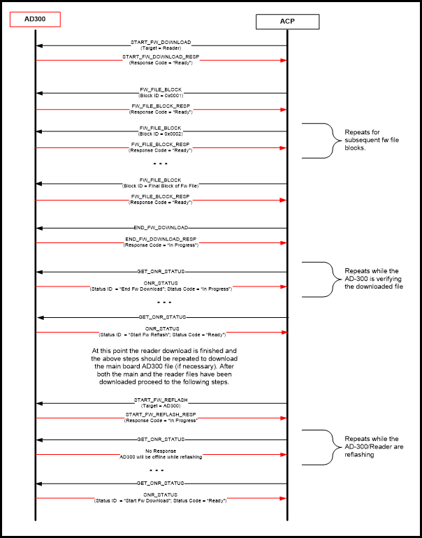
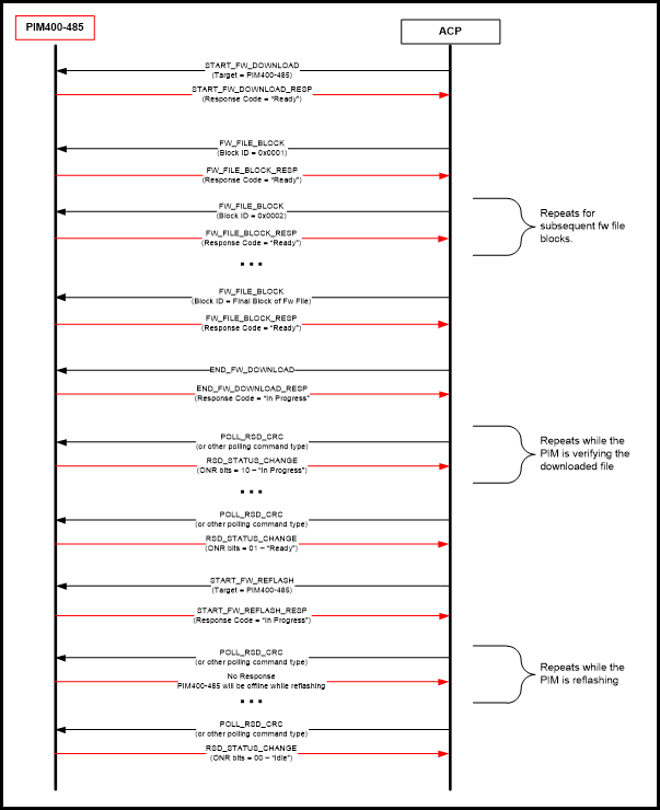
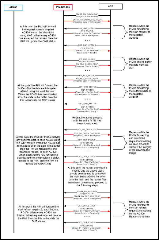
The following diagrams show the basic communication flow between the ACP and an RSD device during the ONR process. These are just typical basic use cases to visually demonstrate some of what is discussed in earlier sections of this document. The polling messaging has been left out of these diagrams to remove the extra clutter. However, in order to maintain full functionality, the ACP has to continue to poll the RSD device throughout the ONR process so that all credential/status updates can be processed.
Some examples are shown using the GET_ONR_STATUS scheme and others with the extended status reporting scheme. Either way is acceptable for all products, even if not explicitly shown in these examples. Since these are only typical use cases it should not be concluded that the AD devices always respond with the indicated response codes. The ACP should be able to correctly handle any of the response codes that are defined in the RSI Protocol. For more detailed examples of RSI traces for the ONR process see other sections of this document.
Example Use Case Figures shown following:
NOTE: The definitions listed below were taken from the RSI Protocol document and for the latest response code listings the RSI Protocol document should be referenced and not the tables that follow.
Any response code that is not listed in the tables or is marked as reserved in the RSI protocol may be used in the future. The ACP should be equipped to handle an undefined response code. The recommendation would be to treat an unknown response code as an unknown error and simply retry the previous message or abort the download.
If the RSD device can quickly process an incoming message and perform all necessary checks then the response code can immediately be provided in the message response. Otherwise the initial response is returned as “In-Progress” and the ONR Status is used to convey any success/failures. As a rule, the AD-300/PIM ONR cases are able to provide more immediate feedback than the AD-400 ONR case. This is because of the extra time associated with forwarding ACP messages from the PIM to the AD-400. The PIM is not able to always make all verifications/decisions on the AD-400s behalf.
NOTE: If an error is reported immediately in a message response it is not updated in the ONR Status, but rather the ONR status retains its current value.
| Response Code | Detailed Meaning | ACP Action to Take |
|---|---|---|
| 0x00 – No Error | The start download request is accepted and the device is now ready to receive FW file data. | Start sending the FW file data using the FW_FILE_BLOCK message. |
| 0x01 – In-Progress | The start download request is received; however, more time is needed to fully verify whether the target can accept the download request. | Start monitoring the ONR status by using the GET_ONR_STATUS message or using the extended polling response and wait for the status to change to indicate success/failure. |
| 0x30 – Error: Incorrect message format | The incoming start FW download message did not include all the necessary information. For example: if the target and/or target bitmap bytes are not included in the message, the ONR download session will not start for any of the targeted devices. | Verify that the message includes all defined bytes as described in the RSI protocol and then resend the message. |
| 0x31 – Error: Already in reflash mode | While the target is preparing to reflash or if an AD-400 linked to a PIM is already reflashing, then a new download session cannot be started. The ONR download session will not start for any of the targeted devices. | Start monitoring the ONR status by using the GET_ONR_STATUS message or if using the extended polling response wait for the status to change to indicate that reflashing has completed and then resend the message. |
| 0x32 – Error: Invalid download target | The target listed in the command does not match the device type at the targeted address. For example, if a download for an MTK reader is requested, but the device installed is a MAG reader, the ONR download session will not start for any of the targeted devices. | Verify the device type at the targeted address and resend the message with the proper target type. |
| 0x33 – Error: Target does not support ONR | The firmware and/or bootloader version of the targeted device is not able to support the ONR process. The ONR download session will not start for any of the targeted devices. | The target device needs to be manually updated (using SUS) to a minimum version before the ONR feature can be used. |
| 0x34 – Error: WOR not enabled | The WOR feature is not enabled. The ONR download session will not start for any of the targeted devices. | Enable the WOR feature using the SET_RSD_WOR command. Recommendation is to use an interval setting of 10 seconds. After WOR is enabled, resend this message. |
| 0x35 – Error: Target WAPM offline | One of the targeted AD-400s is currently offline. The ONR download session will not start for any of the targeted devices. | Wait for the device to come back online and then resend the message. Which device is offline can be obtained by sending the POLL_APM_CRC or POLL_APM_CHECKSUM message to each targeted AD-400. Once it is known which device is offline the other option is to start a download for all those AD-400s that are currently online. |
| 0x36 – Error: Target has low batteries | One of the targeted battery-operated devices is in a low battery state. The ONR download session will not start for any of the targeted devices. | The batteries must be replaced before ONR can begin. Resend the message after replacing batteries. Which device is in a low battery state is determined by sending the POLL_APM_CRC or POLL_APM_CHECKSUM message to each targeted AD-400. Once it is known which device is in a low battery state the other option is to start a download for all those AD-400s that currently have good batteries. |
| Response Code | Detailed Meaning | ACP Action to Take |
|---|---|---|
| 0x00 – No Error | The FW file data is accepted and stored into memory. | Send the next block of the FW file, or if entire FW file has been downloaded, send the end FW download command. |
| 0x01 – In-Progress | The FW file data has been received, however, more time is needed to fully process the data before more can be accepted. A typical use case is that the PIM has a full buffer of data that it needs to forward to the targeted AD-400s. | Start monitoring the ONR status by using the GET_ONR_STATUS message or using the extended polling response and wait for the status to change to indicate success/failure before sending anymore FW file data. |
| 0x40 – Error: Not in active download session | The target device has not received/accepted a start ONR download request, so it is unable to accept FW file data. | Verify that the FW file data is being sent to the correct device. If it is, send the START_FW_DOWNLOAD message to the target to start a new download session. Once the download session is started the FW file data can be accepted starting from block ID 0x0001. |
| 0x41 – Error: Invalid block size received | Only a block size of 64 FW file bytes is accepted in the message. The message received had less/more bytes than 64. | Verify that 64 bytes of FW file data are being sent to the target and resend the message. |
| 0x43 – Error: Out of sequence block ID | The received block ID is greater than the block ID expected. Everytime the target receives a valid block it increments the expected block ID by 1, so the ACP should do the same. | Block IDs with a value less than the expected block ID are accepted. The ACP could try to resend the previous few block ID messages to attempt to re-sync with the target. However, the safest thing to do would be to send the START_FW_DOWNLOAD message to restart the download and restart from block ID 0x0001. |
| 0x44 – Error: Unable to write data to memory | There was a failure when writing the FW file data to eeprom. | This is likely a hardware issue or an issue communicating with the eeprom on the product. Retry the message to attempt to write the data again, however, if all attempts fail this device may need to be upgraded manually or replaced with one that has a working eeprom. |
| 0x45 – Error: Invalid FW file type received | After the header portion of the FW file is received, the file type is checked. If it is detected that the FW file type is not correct for the currently installed device, this error is sent to provide quick feedback rather than wait until the end of the download. For example, if the download is started for the AD-300, but the AD-400 file is sent. | Verify the correct FW file is being sent and restart the download. |
| 0x46 – Error: Invalid FW file version received | After the FW file header is received, the file version is checked. If it is detected that the FW file version is not above a certain threshold to ensure compatibility, this error is sent to provide quick feedback rather than wait until the end of the download. | Verify the correct FW file is being sent and restart the download. |
| 0x47 – Error: Invalid block ID received | Either a block ID of 0x0000 was received or an out-of-range block ID was received meaning that too much data was downloaded already. | Verify the correct ONR FW file is being sent and that the block ID starts at 0x0001 for a file download. |
| 0x49 – Error: Buffer full – not ready for data | The PIM buffers FW file data for the AD-400. When that buffer is full the “In-Progress” response is provided to the FW file block that fills the buffer. If the ACP continues to send data while the buffer is full this response is received. The FW file block that receives this response is not saved. | Monitor the ONR status until it indicates that the device is ready for more data. At that point resend this FW file block and continue the download process. |
| Response Code | Detailed Meaning | ACP Action to Take |
|---|---|---|
| 0x00 – No Error | The CRC validation of the last file downloaded has passed. This file is now ready to be reflashed. | Start a new ONR download to download any other needed files or start a reflash session using the START_FW_REFLASH message. |
| 0x01 – In-Progress | The end download request has been received; however, more time is needed to fully validate the downloaded file. | Start monitoring the ONR status by using the GET_ONR_STATUS message or using the extended polling response, wait for the status to change to indicate success/failure of FW file validation. |
| 0x45 – Error: Invalid FW file type received | Upon re-validation of the FW file header it was found that the file type is not correct for the target device. For example, the file is an AD-400 FW file, but the target device is an AD-300. This was previously checked during the download process, so either the device type was changed (ex: change reader types) or the file has been corrupted. | Verify that the installed hardware has not changed during the download and restart the download process. |
| 0x46 – Error: Invalid FW file version received | Upon re-validation of the FW file header it was found that the FW file version is not above a certain threshold to ensure compatibility. This was previously checked during the download process, so something occurred to corrupt this data. | Restart the download process and try again. |
| 0x50 – Error: Not in active firmware download session | The target device has not received/accepted a start ONR download request and is not pending FW file data that needs validated. | Verify that the end download request is being sent to the correct device. If it is send the START_FW_DOWNLOAD message to the target to start a new download session. Once the download session is started the FW file data can be accepted starting from block ID 0x0001. |
| 0x51 – Error: CRC validation failed | The downloaded file is not valid and cannot be reprogrammed. | Downloaded FW file is corrupt. Verify valid ONR file is being downloaded and that all the data has been downloaded. The download process may need to be restarted. |
| Response Code | Detailed Meaning | ACP Action to Take |
|---|---|---|
| 0x00 – No Error | The abort request is accepted and the targeted device is reset to ONR Idle status | None. |
| 0x60 – Error: Incorrect message format | The incoming abort FW download message did not include all necessary information. For example, if the target bitmap bytes are not included in the message, the ONR download session is not aborted for any of the targeted devices. | Verify that the sent message follows the definition as listed in the RSI Protocol and resend the message. |
| 0x61 – Error: Busy with other ONR target | If it is currently in the middle of the PIM download process and there is a request to abort WAPMs that are linked to that PIM, this type of activity is not supported. | Finish the download to the PIM and resend the abort command to the WAPMs. |
| Response Code | Detailed Meaning | ACP Action to Take |
|---|---|---|
| 0x01 – In-Progress | The start FW reflash request is received; however, it will take more time to fully reprogram the device. | Start monitoring the ONR status by using the GET_ONR_STATUS message or if using the extended polling response wait for the status to change to indicate success/failure of FW reprogramming. |
| 0x70 – Error: Incorrect message format | The incoming start FW reflash message did not include all necessary information. For example, if the target/target bitmap bytes are not included in the message, the ONR reflash session is not started for any of the targeted devices. | Verify that the sent message follows the definition as listed in the RSI Protocol and resend the message. |
| 0x71 – Error: Invalid reflash target | The incorrect target is listed in the reflash command. For example, the command requests to reflash a PIM; however, an AD-300 is currently installed at the targeted address. | Verify the correct device is installed at the targeted address and resend the message. |
| 0x72 – Error: No valid FW file downloaded | No valid FW file is currently pending reflashing in the target device. It has either already been reflashed, no file has been downloaded since last reflashing or the downloaded file was invalid. | A downloaded FW file can only be reflashed a single time, so restart a new download and then reflash once re-downloaded. |
| 0x73 – Error: FW file in process of being verified | The device is busy processing the end FW download request. It cannot be reflashed until the verification is complete. | Monitor the ONR status until it updates to indicate whether the FW file verification succeeds/fails. |
| 0x74 – Error: Busy with other ONR activity | The device is in the middle of a download session and cannot be reflashed. | Send GET_ONR_STATUS to determine the current state of the device and take appropriate action by either finishing the current download or restarting and completing a new download prior to attempting to reflash. |
| 0x75 – Error: WOR not enabled | The WOR feature has not been enabled. The ONR download session is not started for any of the targeted devices. | Enable the WOR feature using the SET_RSD_WOR command. Recommendation is to use an interval setting of 10 seconds. After WOR is enabled, resend this message. |
| Status Code | Detailed Meaning | ACP Action to Take |
|---|---|---|
| 0x00 – No Error | The device is in an ONR idle state and awaiting the start of a download session. No FW file is pending reflashing. | Start a new ONR download session by sending the START_FW_DOWNLOAD message. |
| 0x01 – In-Progress | The start download request is received; however, more time is needed to fully verify whether the target can accept the download request. | Continue monitoring the ONR status by using the GET_ONR_STATUS message or using the extended polling response. Wait for the status to change to indicate success/failure. |
| 0x02 – In-Progress, but waiting for WOR to be enabled | The WOR feature is enabled in the PIM; however, the PIM still needs to enable the feature in each of its linked AD-400s. Once this is complete, the start FW download message is forwarded and processed. This could take up to the AD-400 heartbeat time (default 10 min). | Continue monitoring the ONR status by using the GET_ONR_STATUS message or using the extended polling response. Wait for the status to change to indicate success/failure. |
| 0x10 – Target WAPM currently offline | The target AD-400 is currently offline. The PIM waits for the lock to come back online and at that time it forwards the start FW download message, so it can be processed by the device. | Continue monitoring the ONR status by using the GET_ONR_STATUS message or using the extended polling response. Wait for the status to change to indicate success/failure. If the ACP does not want to wait for this device, it can be aborted so the process can continue with other remaining AD-400s linked to this PIM. |
| 0x21 – Error: Power cycle occurred | The PIM has reset during the process of forwarding the start FW download message to each device. The PIM has lost track of the targeted devices in the start download message, so the message must be resent by the ACP. | This is unrecoverable; the ACP must restart the download. |
| 0x22 – Error: Unknown Issue | There has been an unexpected fault in the device firmware while processing the ONR commands. | This is unrecoverable; the ACP must restart the download |
| 0x23 – Error: Reader not responding to ONR command | The reader module is not responding to ONR requests from the main board. All retry attempts have been exhausted and the main board and PIM will enter an ONR failure state. | This is unrecoverable; the ACP must restart the download. If failures continue someone will need to visit the device to determine what is going on. |
| 0x32 – Error: Invalid start FW download target received | The target listed in the command does not match the device type at the targeted address. For example, if a download for an MTK reader is requested, but the device installed is actually a MAG reader. The ONR download session will not be started for any of the targeted devices. | Verify the device type at the targeted address and resend the message with the proper target type. |
| 0x33 – Error: Target does not support ONR download | The firmware and/or bootloader version of the targeted device is not able to support the ONR process. The ONR download session will not be started for any of the targeted devices. | The target device needs to be manually updated (using SUS) to a minimum version before the ONR feature can be used. |
| 0x34 – Error: WOR not enabled, unable to send start FW download request to target | The WOR feature has not been enabled. The ONR download session will not be started for any of the targeted devices. | Enable the WOR feature using the SET_RSD_WOR command. Recommendation is to use an interval setting of 10 seconds. After WOR is enabled, then resend this message. |
| Status Code | Detailed Meaning | ACP Action to Take |
|---|---|---|
| 0x00 – No Error | The FW file data is accepted and stored into memory. | Send the next block of the FW file, or if complete send the end FW download command. |
| 0x01 – In-Progress | The FW file data is received, however, more time is needed to fully process the data before more can be accepted. Typical use case is that the PIM has a full buffer of data that it needs to forward to the targeted AD-400s. | Continue monitoring the ONR status by using the GET_ONR_STATUS message or using the extended polling response. Wait for the status to change to indicate success/failure before sending anymore FW file data. |
| 0x10 – Target WAPM currently offline | The target AD-400 is currently offline. The PIM waits for the device to come back online and at that time forwards the FW file data so it can be processed by the device. | Continue monitoring the ONR status by using the GET_ONR_STATUS message or if using the extended polling response. Wait for the status to change to indicate success/failure. If the ACP does not want to wait for this device, it can be aborted so the process can continue with remaining AD-400s linked to this PIM and involved in the ONR session. |
| 0x11 – Resend previous FW file block | The AD-300/PIM has reset during the download process. This is recoverable assuming the ACP still knows where in the download process the target left off. | To be safe the ACP should send the previous block ID of firmware just to ensure that it was properly stored and not lost during the power cycle. |
| 0x21 – Error: Power cycle occurred | The PIM has reset during the process of downloading information to the AD-400. The PIM has lost track of what information has been downloaded to which device, so the ONR process must be restarted by the ACP. | This is unrecoverable; the ACP must restart the download. |
| 0x44 – Error: Unable to write data to memory | There was a failure when writing the FW file data to eeprom. | This is likely a hardware issue or issue communicating with the eeprom on the product. Retry the message to attempt to write the data again, however, if all attempts fail this device may need to be upgraded manually or replaced with one that has a working eeprom. |
| 0x45 – Error: Invalid FW file type received | After the FW file header is received, the file type is checked. If it is detected that the FW file type is not correct for the currently installed device, this error is sent to provide quick feedback rather than wait until the end of the download. For example, if the download is started for the AD-300, but the AD-400 file is sent. | Verify the correct FW file is being sent and restart the download. |
| 0x46 – Error: Invalid FW file version received | After the FW file header is received, the file version is checked. If it is detected that the FW file version is not above a certain threshold to ensure compatibility, this error is sent to provide quick feedback rather than wait until the end of the download. | Verify the correct FW file is being sent and restart the download. |
| 0x47 – Error: Invalid block ID received | Either a block ID of 0x0000 was received or an out of range block ID was received meaning that too much data has been downloaded already. | Verify the correct FW file is being sent and that the block ID starts at 0x0001 for a file download. |
| 0x48 – Error: WOR is not enabled, unable to send FW file block request to target | The WOR feature is disabled during the ONR process. | Enable the WOR feature using the SET_RSD_WOR command. Recommendation is to use an interval setting of 10 seconds. After WOR is enabled, restart the ONR download. |
| Status Code | Detailed Meaning | ACP Action to Take |
|---|---|---|
| 0x01 – In-Progress | The end download request is received; however, more time is needed to fully validate the downloaded file. | Continue monitoring the ONR status by using the GET_ONR_STATUS message or using the extended polling response. Wait for the status to change to indicate success/failure of FW file validation before attempting to reflash. |
| 0x10 – Target WAPM currently offline | The target AD-400 is currently offline. The PIM waits for the device to come back online and at that time forwards the end FW download message so it can be processed by the device. | Continue monitoring the ONR status by using the GET_ONR_STATUS message or using the extended polling response. Wait for the status to change to indicate success/ failure. If the ACP does not want to wait for this device it can be aborted so the process can continue with other AD-400s linked to this PIM. |
| 0x21 – Error: Power cycle occurred | The PIM has reset during the process of forwarding the end FW download message to each device. The PIM has lost track of the status of each of the AD-400s, so the ONR process must be restarted. | This is unrecoverable; the ACP must restart the download. |
| 0x45 – Error: Invalid FW file type received | The FW file header is re-validated as part of end FW download processing. If it is detected that the FW file type is not correct for the currently installed device, this error is sent to provide quick feedback rather than wait until the end of the download. For example, if the download is started for the AD-300, but the AD-400 file is sent. | Verify the correct FW file is being sent and then restart the download. |
| 0x46 – Error: Invalid FW file version received | The FW file header is re-validated as part of end FW download processing. If it is detected that the FW file version is not above a certain threshold to ensure compatibility, this error is sent to provide quick feedback rather than wait until the end of the download. | Verify the correct FW file is being sent and then restart the download. |
| 0x51 – Error: CRC validation failed | The downloaded file is not valid and cannot be reprogrammed. | Downloaded FW file is corrupt. Verify that the valid ONR file is being downloaded and that all the data has been downloaded. May need to restart the download process. |
| 0x52 – Error: WOR is not enabled, unable to send end FW download request to target | The WOR feature is disabled during the ONR process. | Enable the WOR feature using the SET_RSD_WOR command. Recommendation is to use an interval setting of 10 seconds. After WOR is enabled, restart the ONR download. |
| Status Code | Detailed Meaning | ACP Action to Take |
|---|---|---|
| N/A | This status identifier is currently reserved for future use. The current implementation of FW should not be using this status ID. | ACP should be able to not choke on this status ID, should it be used in future revisions. If this is received, the ACP should retry whatever action it is currently doing and if that fails restart the ONR process. |
| Status Code | Detailed Meaning | ACP Action to Take |
|---|---|---|
| 0x00 – No Error | The downloaded file or files have been verified and are ready to be reflashed. | Send the request to start the reflash procedure or if there are more files to be downloaded then start a new ONR download session |
| 0x01 – In-Progress | The start FW reflash request is received; however, it will take more time to fully reprogram the device. | Continue monitoring the ONR status by using the GET_ONR_STATUS message or using the extended polling response. Wait for the status to change to indicate success/failure of FW reprogramming. |
| 0x02 – In-Progress, but waiting for WOR to be enabled | The WOR feature is enabled in the PIM; however, the PIM still needs to enable the feature in each of its linked AD-400s. Once this is complete the start FW reflash message is forwarded and processed. | Continue monitoring the ONR status by using the GET_ONR_STATUS message or using the extended polling response. Wait for the status to change to indicate success/failure. |
| 0x10 – Target WAPM currently offline | One or more target AD-400s are currently offline. The PIM waits for the device to come back online and at that time forwards the start FW reflash message, so it can be processed by these devices. Other devices not offline continue to be reflashed. | Continue monitoring the ONR status by using the GET_ONR_STATUS message or if using the extended polling response. Wait for the status to change to indicate success/failure. If the ACP does not want to wait for this device, it can be aborted so the process can continue with other AD-400s linked to this PIM. |
| 0x21 – Error: Power cycle occurred | The PIM has reset during the process of forwarding the start FW reflash message to each device. The PIM has lost track of the targeted devices in the start reflash message. Some of the devices may have reflashed prior to reflashing; there is no way for the PIM to tell. | This is unrecoverable; the ACP must restart the process. The firmware versions of the targets should be checked to see which ones have reflashed and which ones have not. |
| 0x45 – Error: Invalid FW file type received | The FW file header is re-validated as part of the start FW reflash processing. This was verified during previous steps but checked again prior to reflashing. For example, if the download is started for the AD-300, but the AD-400 file is sent. | Verify the correct FW file is being sent and then restart the download. |
| 0x46 – Error: Invalid FW file version received | The FW file header is re-validated as part the of start FW reflash processing. This was verified during previous steps but checked again. | Verify the correct FW file is being sent and then restart the download. |
| 0x51 – Error: CRC validation failed | The downloaded file is not valid and cannot be reprogrammed. | Downloaded FW file is corrupt. Verify valid ONR file is being downloaded and that all the data has been downloaded. The download process may have to be restarted. |
| 0x75 – Error: WOR is not enabled, unable to send start FW reflash request to target | The WOR feature is disabled during the ONR process. | Enable the WOR feature using the SET_RSD_WOR command. Recommendation is to use an interval setting of 10 seconds. After WOR is enabled, restart the ONR download. |
| 0x76 – Error: WAPM reflash timed out | One or more AD-400s acknoweldged the receipt of the START_FW_REFLASH message, however, it has failed to report that reflashing was successful. | Need to visit the device to determine if device is functional or not. It could have just been a communication issue, or the device could be stuck in its bootloader. |
The Secure Communication method feature, described in this section, enables the ACP to communicate with the RSD in a secure manner, where important commands/responses exchanged between the ACP and the RSD are encrypted. Secure Communication between the ACP and the RSD uses an encryption method known as Advanced Encryption Standard (AES) 128 bit in ECB (Electronic Codebook) mode. Secure Communication method requires the ACP to follow certain procedures to establish the secure communication with the RSD. Major components of the Secure Communication method are explained in detail in the following sections.
Key Types: Defines different keys used during secure communication.
Secure Session: A period during which an ACP can communicate with the RSD in a secure manner.
Key Change: Defines procedure to replace the existing key or to set the new key.
Key Life Cycle: Defines key’s life cycle (FDR, Firmware upgrade/downgrade).
This feature is configurable. An ACP can enable or disable Secure Communication mode on the fly using provided RSI commands. For the out-of-the-factory device or after the first-time firmware upgrade to the version which supports this feature, this feature is disabled.
NOTE: For the remainder of this document, this feature is called Secure Mode.
Currently PIM400-485 and AD-300 devices support Secure Mode over the RS-485 bus. Minimum firmware version requirements for these devices are listed below:
PIM400-485-RSI: 2.24.2 (Package - AD.A.70)
PIM400-485-VBB:2.24.2 (Package - AD.A.70)
AD-300 Main Board: 2.44.2 (Package - AD.A.70)
The limitations and requirements needed to support this feature are listed below:
Once the Secure Mode is enabled, broadcast messages are not supported by the RSD.
With the PIM-AD-400 setup, during Secure Communiation, all APM addressed commands should be addressed to the PIM to which that APM is linked. The ACP should know beforehand which APM (AD-400) is linked to which PIM.
During the Secure Communication, each RSD has a unique Session Key which is different from the other RSD. The ACP should be able to handle multiple Keys for RSDs connected in the network.
Secure Communication method defines three keys used at different stages of secure communication.
Default Key
Allegion Default Key: 68C1D69B429CC14587822B0A369CFFE0
ACP Default Key
Master Key
Session Key
Initial Default Key is the Allegion Default Key. The Allegion Default Key is active when there is no ACP Default Key or no Master Key set in the RSD. The Default Key can establish only Admin Secure Session to set the new Master Key or to set the ACP Default Key. The Default Key cannot be used to create Normal Secure Session for secure communication with the RSD. Once the Master Key is set, the Default Key is no longer active.
Master Key is used to establish Secure Session (Admin/Normal). Once the Master Key is set, ACP can establish the Normal Secure Session and start communicating securely with the RSD. Master Key is mandatory to establish the Normal Session.
Session Key is the encryption key derived during establishing the Secure Session. Session Key is used to encrypt commands/responses exchanged during the the Secure Session. Session Key is valid only during that specific session. Once the session ends, Session Key for that session is no longer valid.
Secure Session is a period during which an ACP can communicate with the RSD in a secure manner. For any meaningful communication between the ACP and the RSD, ACP needs to establish the Secure Session first. To establish the Secure Session, ACP needs to follow a specific procedure which is given in the Establishing the Secure Session section below.
NOTE: When Secure Mode is enabled, and a Secure Session is not established, RSD falls offline and grants access from the cache. In this state, RSD responds to any command (except to initiate Secure Session) sent by the ACP with an error indicating session not established in SECURE_MODE_STATUS_REP response.
RSI Secure Communication method defines two types of Secure Sessions for different purposes.
Admin Secure Session
Normal Secure Session
During Admin Secure Session, RSD only allows the following commands to modify Secure Mode related configurations.
RSD_SET_ACP_KEY:
To set or replace ACP Default Key or Master key.
RSD_SECURE_HOST_CONFIG:
To modify Secure Mode related configuration such as Session timeout and Default Key selection.
RSD_START_SECURE_SESSION:
To initiate the new Normal/Admin Secure Session.
For all other commands (including POLL messages) sent by the ACP, RSD responds with RSD_SECURE_MODE_STATUS_RESP with an error indicating command not supported during current session. Sending these commands does not cause session termination by the RSD.
During the Admin Secure Session, since the RSD does not report any card data or status change to the ACP, it is advised to keep Admin Secure Session as short as possible. However, during this session, once ACP timeout occurs, RSD falls offline and grants access from the cache (AD-300 falls offline and PIM400 stops communicating to the AD-400).
During the Normal Secure Session, RSD allows all commands except the commands to set/replace Default or Master key (RSD_SET_ACP_KEY) and to modify the Secure Mode related configurations (RSD_SECURE_HOST_CONFIG). Once the Normal Secure Session is established, RSD comes back online and starts processing normal RSI protocol commands and starts reporting status change and card data encrypted using the Session key.
The Secure Session establishment procedure can only be initiated by the ACP. RSD does not initiate the Secure Session by itself. To establish a Secure Session, ACP needs to follow the specific procedure described below:
The Secure Session establishment procedure ensures that:
the Session Key is created with the involvement of both the ACP and the RSD, and
both, the ACP and RSD are sharing the common key (by mutual authentication between the ACP and the RSD).
Table 9-1 shows the command/response pairs added to the existing RSI Protocol to facilitate the Secure Session establishment.
| Command | Response |
|---|---|
| RSD_START_SECURE_SESSION ACP requests to initiate the new Secure Session. | RSD_START_SECURE_CHALLENGE RSD provides the challenge. |
| RSD_START_SECURE_SESSION_ACK ACP provides proof that it knows the current active Key, provides its own challenge and asks for similar proof from the RSD. | RSD_START_SECURE_SESSION_COMPLETE RSD provides the proof that it knows the current active Key. |
To initiate the Secure Session, ACP sends RSD_START_SECURE_SESSION command to the RSD. This command can be sent anytime once the Secure Mode is enabled.
ACP->RSD: RSD_START_SECURE_SESSION
| Byte | Field | Data/Description | |
|---|---|---|---|
| 1 | Start of Frame | 0AH | |
| 2 | RSD address | 00H to FEH & not AAH | |
| 3 | Type | 20H | |
| 4 | Length | 04H | |
| 5 | Data | 1 byte | Sub command: 01H |
| 1 byte | 00H = Establish Normal Secure Session. 01H = Establish Admin Secure Session. 02H – FFH = RFU (should be zero) | ||
| 2 bytes | Reserved for future. | ||
| 9/10 | Frame check sequence | CRC or CHECKSUM |
Data Byte 6th (Payload byte 2nd) indicates what type of Secure Session (Admin/Normal) needs to be established. After receiving this command, RSD terminates the existing Secure Session (if established) and responds with the RSD Random Number encrypted using the current active Key.
RSD->ACP: RSD_START_SECURE_SESSION_CHALLENGE:
| Byte | Field | Data/Description | |
|---|---|---|---|
| 1 | Start of Frame | 0AH | |
| 2 | RSD address | FFH | |
| 3 | Type | 21H | |
| 4 | Length | 11H | |
| 5 | Data | Byte 1 | Sub command: 01H |
| Byte 2-17 | Encrypted and permuted RSD Random Number | ||
| 22/23 | Frame check sequence | CRC or CHECKSUM |
After receiving above response from the RSD, ACP performs the following steps to retrieve the RSD Random Number.
Decrypt the 16 bytes response.
Rotate the decrypted result to the left by one byte.
Retrieve the RSD Random Number from the first 8 bytes. Lower 8 bytes are null padding bytes which are discarded by the ACP.
Once the RSD Random Number is retrieved, ACP prepares the payload for the next command to be sent to the RSD to establish the Secure Session.
ACP generates the 8-byte ACP Random Number.
Appends ACP Random Number to the RSD Random Number and prepares 16 bytes of data block.
Rotates the result to the right by one byte.
Prepares the payload for the next command (RSD_START_SECURE_SESSION_ACK) by encrypting the above result using the current active Key.
ACP->RSD: RSD_START_SECURE_SESSION_ACK
| Byte | Field | Data/Description | |
|---|---|---|---|
| 1 | Start of Frame | 0AH | |
| 2 | RSD address | 00H to FEH & not AAH | |
| 3 | Type | 20H | |
| 4 | Length | 11H | |
| 5 | Data | 1 byte | Sub command: 02H |
| 16 byte | Encrypted and Permuted RSD Random Number and ACP Random Number. | ||
| 22/23 | Frame check sequence | CRC or CHECKSUM |
After receiving the above command from the ACP, RSD retrieves RSD Random Number from the encrypted payload and verifies that the same Random Number was provided by the RSD in the previous command’s response. This way, RSD authenticates the ACP and confirms that the ACP is legitimate. RSD prepares response to this command by encrypting the ACP Random Number and sending it to the ACP.
RSD->ACP: RSD_START_SECURE_SESSION_COMPLETE
| Byte | Field | Data/Description | |
|---|---|---|---|
| 1 | Start of Frame | 0AH | |
| 2 | RSD address | FFH | |
| 3 | Type | 21H | |
| 4 | Length | 11H | |
| 5 | Data | Byte 1 | Sub command: 02H |
| Byte 2-17 | Encrypted and Permuted ACP Random Number | ||
| 22/23 | Frame check sequence | CRC or CHECKSUM |
After receiving above response from the RSD, ACP performs below process to retrieve the ACP Random Number.
Decrypt the 16 bytes response.
Rotate the decrypted result to the left by one byte.
Retrieve the ACP Random Number from the first 8 bytes. Lower 8 bytes are null padding bytes which are discarded by the ACP.
Once the ACP Random Number is retrieved from the response, ACP compares it with the Random Number which was sent encrypted in the command. If the ACP Random Number matches, ACP assumes that the RSD is legitimate.
After the ACP authenticates the RSD, ACP derives the Session Key based on the ACP Random Number and RSD Random Number described in the next section.
To derive the Session Key, the ACP follows these steps:
Concatenate the RSD Random Number and the ACP Random Number and prepare the 16 bytes data block.
Rotate the above 16 bytes to the right by one byte.
Swap 1st, 2nd, 3rd and 4th byte with 9th, 10th, 11th and 12th bytes respectively.
Session timeout is a non-volatile setting in the RSD indicating secure session expiration. After session timeout, RSD terminates the secure session by itself. In this case, ACP establishes the new secure session again. RSD session timeout can be set by the ACP using RSD_SECURE_HOST_CONFIG command. Session timeout cannot be set as 0. Session timeout value ranges from 1 to 65535 minutes.
Once the Secure Session is established, the ACP and the RSD, both maintain two sequence numbers to prevent against the replay attack. One sequence number is the ACP Sequence Number which is sent by the ACP in the encrypted command and another sequence number is the RSD Sequence Number which is sent by the RSD in the encrypted response.
When the ACP sends a command, it adds ACP Sequence Number to the encrypted command packet starting at 0001H and increments everytime it sends another command. At the other end, the RSD receives the command and compares it to its own copy of the ACP Sequence Number. If the received ACP Sequence Number is lower than or greater than 4 of the RSD’s copy of the ACP Sequence Number, the RSD terminates the Secure Session.
When the RSD responds with the encrypted response, it adds RSD Sequence Number to the encrypted command and increments everytime it sends another encrypted command. When ACP receives the command, it compares the received RSD Sequence Number to its own copy of RSD Sequence Number and if it is not in the allowable range, it assumes that the response received is from the illegitimate RSD and either should terminate the Session and try to create a new Session or should not respond to that RSD further.
The allowable range for Sequence Number is: current Sequence Number < Sequence Number received in Message < current Sequence Number + 4. Once the Sequence Number rolls over (reaches FFFFH), the RSD terminates the existing Secure Session and reports the error to the ACP in SECURE_MODE_STATUS_RESP indicating that Session terminated due to Sequence Number roll over.
RSD terminates the Secure Session if any of the following events occur:
RSD reset
FDR
Firmware Upgrade/Downgrade
Certain errors during Secure Session
If Sequence Number in received command is not in valid range
Consequetive three times Secure CRC mismatch
Sequence Number rollover
ACP sends new Secure Session initiation request (RSD_START_SECURE_SESSION)
ACP can only replace RSD’s ACP Default Key or Master Key during Admin Secure Session. During the Normal Secure Session, RSD’s Key change is not allowed. Newly updated Key is valid from the next Secure Session onward.
RSD’s Default Key (Allegion Default Key as well as ACP Default Key) are active/valid only when:
there is no Master key set in the RSD such as after level 1 FDR
for the first time use of this feature
the out-of-factory RSD
After level 1 FDR, the Allegion Default Key as well as the ACP Default Key (if set earlier by the ACP), both becomes valid and ACP can select either keys to initiate Secure Session.
While enabling the Secure Mode, ACP can send GET_SECURE_MODE_STATUS command to know if the ACP Default Key is set earlier on the RSD and using SECURE_HOST_CONFIG command, ACP can configure the RSD to use either of the Default Keys.
Master Key is cleared after level 1 FDR is performed. Master Key is not affected during firmware upgrade/downgrade, reset or any other event except level 1 FDR.
Session Key is a transient Key stored in RAM. Session Key is cleared after Secure Session is terminated due to any reason (see Secure Session Termination section above). In case of Comm Loss scenario, RSD keeps Secure Session alive, so Session Key is still valid once RSD comes back online.
Secure Mode is disabled by the RSD in the FDR condition. The RSD works in normal mode (without RSI encryption) in factory configuration. When secure mode is disabled, RSD ignores any encrypted command received and does not respond to that encrypted command.
Initially, out-of-the-factory, RSD only has the Allegion Default Key. Once ACP enables the Secure Mode for the first time, ACP may choose to set the ACP Default Key. On subsequent FDRs, both the Allegion Default Key as well as the ACP Default key become valid and ACP may choose either of the Default Keys while enabling the Secure Mode.
Table 9-2 indicates the status of the nonvolatile settings for RSD in FDR state. These settings can be configured by the ACP using RSD_SECURE_HOST_CONFIG command.
| Keys/Other configuration | Factory Default Configuration/after FDR/Re-class |
|---|---|
| Status | |
| Allegion Default key and ACP Default Key (If set earlier) | VALID |
| Master key | CLEARED (INVALID) |
| Secure Session Timeout | 0xFFFF (65535 minutes) |
| RSI encryption feature (Secure Mode) | DISABLED |
Secure Mode is a configurable feature and can be enabled or disabled by the ACP using RSD_SECURE_HOST_CONFIG RSI command. When Secure Mode is not enabled, this command can be sent by the ACP any time unencrypted. This command also modifies other configurable settings such as the Session Timeout and the Default Key Selection. ACP can set other settings along with enabling Secure Mode. In certain scenarios such as after an FDR (where Secure Mode was enabled earlier and ACP Default Key was set), while enabling the Secure Mode again, if ACP wants to use the ACP Default Key instead of the Allegion Default Key, then in general, ACP should first send GET_RSD_SECURE_MODE_STATUS command to know whether the ACP Default Key is set or not. If ACP Default Key is set, ACP should send RSD_SECURE_HOST_CONFIG with Secure Mode enabled and selecting ACP Default Key.
Once the Secure Mode is enabled, ACP can disable Secure Mode by sending the same RSD_SECURE_HOST_CONFIG command, but this command has to be sent encrypted using the Session Key during the Admin Secure Session. This way it can ensured that the Secure Mode can only be disabled if ACP has knowledge of RSD’s current active Key.
During the Secure Session, any command/response (except certain commands/responses which are not required to be encrypted) exchanged between the ACP and the RSD follows the format shown below in Table 9-3. Original Command/Response are encrypted and wrapped under below encrypted command/Response type (2EH/2FH).
| Field | Field length (bytes) | Description |
|---|---|---|
| Start of Frame | 1 | Start of packet |
| Address | 1 | RSD address to which packet is being sent. (0xFF for response from the RSD) NOTE: This must be the RSD’s address always. Even if the original command is intended for APM (for example APM_LOCK_CONTROL or APM_TIMED_UNLOCK), this address field should always contain RSD’s address (of RSD/PIM to which APM is connected) instead of APM’s address. The encrypted payload should contain the original APM’s address. |
| 1 | Secured command/Response type indicating encrypted command/response. (not the original command type) Command from the ACP: 2EH (RSD_SECURE_COMMAND) Response from the RSD: 2FH (RSD_SECURE_RESPONSE) | |
| Length | 1 or 2 | Length of the payload (variable) |
| (1 or 2 bytes) | ||
| Data | Variable | Encrypted original command/Response |
| Frame Check Sequence (Final CRC) | 1 or 2 | CRC or Checksum |
The payload for the above encrypted command/response has the original command/response encrypted using the Session Key in the format shown in Table 9-4.
| Encrypted data payload | ||||||
|---|---|---|---|---|---|---|
| Sequence Number (2 bytes) (LSB, MSB) | Original RSD/APM address | Original Command/Response type | Length of Payload (excluding Secure CRC/Checksum and padding bytes) (1 or 2 bytes) | Payload | Checksum/CRC (Secured Checksum/CRC) (1-2 bytes) | Padding bytes (if length is not multiple of 16) |
NOTES:
Command TYPE 2EH indicates it is the encrypted command sent by the ACP. TYPE 2FH indicates it is the encrypted response message from the RSD.
Encrypted command messages always have RSD address in the “Address” field. For the RSD command messages, Address field has the RSD address and the same is set in encrypted data. For the APM command messages, Address field has the RSD address (of RSD (PIM) to which APM (AD-400) is connected) and original APM address is set in encrypted data.
In case of response messages sent by the RSD, “Original RSD/APM address” field is always 0xFF.
Padding bytes should always be zeros.
Secure CRC/Checksum can be calculated as shown below:
Secured CRC = CRC16[Concat(Sequence Number, Original RSD/APM address, original command type, length, payload]
Secured Checksum = Checksum[Concat(Sequence Number, Original RSD/APM address, original command type, length, payload]
Secured CRC/Checksum is used to check the integrity of the payload after decryption of the message. Secure CRC/Checksum verification ensures that message encryption was done using correct session key. RSD verifies secure CRC or checksum based on the last received POLL message from the ACP. If last received POLL message is POLL_RSD/APM_CRC, the RSD verifies the secure CRC in encrypted payload and sends out responses with secure CRC. If the last received message is POLL_RSD/APM_CHECKSUM, the RSD verifies the secure checksum in encrypted payload and sends out responses with the Secure Checksum.
RSD_SECURE_MODE_STATUS_RESP is the Secure Mode status reponse reported by the RSD in response to GET_RSD_SECURE_MODE_STATUS command. This response is also sent by the RSD in case any error occurred during the Secure Session or while processing certain Secure Mode related commands. This response is sent by the RSD to report current Secure Mode status related information and to report various errors during the Secure Session. Since once Secure Mode is enabled, RSD can send this reponse any time in response to any RSI command sent by the ACP, ACP should be able to handle this response message anytime as a response from the RSD to any ACP command.
This Secure Mode status response contains Secure Mode status related information in payload data byte 2 and current Secure Mode related error in payload data byte 3.
The following two tables; Table 9-5 and Table 9-6 show the Secure Mode Byte Definition for both Status and Error Codes.
| Bit | Description | Usage |
|---|---|---|
| Bit 7 | RFU (will be zero) | N/A |
| Bit 6 | RFU (will be zero) | N/A |
| Bit 5 | Selected Default Key 1 – ACP Default Key is selected 0 – Allegion Default Key is selected | This bit indicates whether the current selected Default Key is either the ACP Default Key or the Allegion Default Key. |
| Bit 4 | Master Key Info 0 – Master Key is not set 1 – Master Key is set | This bit indicates whether the Master key is set or not. Once Master Key is set, Master Key become active and Default Key will become inactive. So for all further Secure Session establishments, RSD will use Master Key. |
| Bit 3 | ACP Default Key Info 0 – ACP Default Key is not set 1 – ACP Default Key is set | This bit indicates whether the ACP Default Key is set or not. Once ACP sets Default Key, this bit becomes one and ACP Default Key will become the selected Default Key (Indicated in Bit 5) |
| Bit 2 | Admin Secure Session Info 0 – Admin Secure Session is not active 1 – Admin Secure Session is active | This bit indicates whether the Admin Secure Session is established or not. |
| Bit 1 | Normal Secure Session Info 0 – Normal Secure Session is not active 1 – Normal Secure Session is active | This bit indicates whether the Normal Secure Session is established or not. If Secure Session is not established, both Bit 1 and Bit 2 will be zero indicating that Secure Session is not established. |
| Bit 0 | Secure Mode feature 0 – Secure Mode is not enabled 1 – Secure Mode is enabled | This bit indicates whether the Secure Mode is enabled or not. |
| Error Code | Command | Meaning | Detail Description |
|---|---|---|---|
| 0x01 | To any Command (Except for RSD_START_SECURE_SESSION) | Session is not established | When Secure Mode is enabled, and the Secure Session is not established, RSD responds with the RSD_SECURE_MODE_STATUS_RESP with error code 0x01 to all commands sent by the ACP. In this scenario, ACP initiates the Admin or Normal Secure Session. |
| 0x02 | To certain commands during Secure Session | Command is not supported during current Secure Session. | During Secure Session if command is sent which is not allowed during that Secure Session, RSD responds with this error code. During Admin Secure Session, if a command other than RSD_ SET_ACP_KEY, RSD_SECURE_HOST_CONFIG and RSD_START_SECURE_SESSION are sent to the RSD, RSD responds with this error code. During Normal Secure Session, if RSD_ SET_ACP_KEY or RSD_SECURE_HOST_CONFIG is sent, RSD responds with this error code. ACP is not supposed to send not allowed commands during Secure Session. |
| 0x04 | To any command (During Secure Session) | Unencrypted command is not allowed during Secure Session. | When any command (except certain commands) is sent unencrypted during Secure Session, RSD responds with this error code. |
| 0x05 | To any command (During Secure Session) | Session is terminated due to Session timeout. | When Session timeout occurs during a Secure Session, RSD responds with this error code to the next received command. This error is reported only once. After that, the Session terminates and RSD starts reporting error 0x01 to all ACP commands. |
| 0x06 | To any command (During Secure Session) | Session is terminated due to RSD Sequence Number roll over. | When RSD sequence number rolls over, RSD reports this error code to the next received command. This error is reported only once. After that, the Session terminates and RSD starts reporting error 0x01 to all ACP commands. |
| 0x07-0x0F | RFU | N/A | N/A |
| 0x10 | RSD_START_SECURE_SESSION | RSD_START_SECURE_SESSION Command length is invalid | When command is sent with invalid payload length, this error is reported by the RSD in response to the RSD_START_SECURE_SESSION. |
| 0x11 | RSD_START_SECURE_SESSION | Invalid Session type | When command is sent with incorrect Session type (Except Normal (0x01) or Admin (0x00)) while initiating the Secure Session. |
| 0x12 | RSD_START_SECURE_SESSION | Normal Secure Session establishment is not allwed | When Master Key is not set, and ACP tries to initiate Normal Secure Session. When Master key is not set, only Admin Secure Session is allowed using current active Default Key (Allegion/ACP Default Key) |
| 0x13-0x1F | RFU | N/A | N/A |
| 0x20 | RSD_START_SECURE_SESSION_ACK | Invalid Command length | When command is sent with incorrect payload length, RSD responds with this error code. |
| 0x21 | RSD_START_SECURE_SESSION_ACK | RSD Random Number mismatch | When command is sent with payload containing RSD Random Number encrypted using incorrect Key. E.g. When selected Default Key is the ACP Default Key and while establishing Secure Session, ACP sends this command with payload encrypted using Allegion Default Key. |
| 0x22-0x2F | RFU | N/A | N/A |
| 0x30 | RSD_SECURE_HOST_CONFIG | Invalid Command length | When command is sent with incorrect payload length, RSD responds with this error code. |
| 0x31 | RSD_SECURE_HOST_CONFIG | Incorrect Secure Mode Config value | When command is sent with neither Secure Mode “Enable (0x01)” nor “Disable (0x00)”, RSD responds with this error code. |
| 0x32 | RSD_SECURE_HOST_CONFIG | Incorrect Session timeout value | When command is sent with Session timeout set to 0x0000, RSD responds with this error. Zero Session timeout is not allowed. |
| 0x33 | RSD_SECURE_HOST_CONFIG | Incorrect Selected Default Key | When command is sent with selecting ACP Default Key, but ACP Default Key is not set, RSD responds with this error. |
| 0x34-0x3F | RFU | ||
| 0x40 | RSD_SECURE_COMMAND (0x2E) | Incorrect Command length | When Encrypted Command payload is not a multiple of 16, RSD responds with this error. |
| 0x41 | RSD_SECURE_COMMAND (0x2E) | Session terminated due to Sequence Number mismatch | When encrypted command has a sequence number which is not in the allowable range. Valid sequence number range is current ACP Sequence Number < Recevied ACP Sequence Number < current ACP Sequence Number + 4. |
| 0x42 | RSD_SECURE_COMMAND (0x2E) | Secure CRC/Checksum mismatch | When encrypted command’s Secure CRC/Checksum is not correct (probable scenario is where ACP does not use correct Session Key to encrypt the command), RSD responds with this error. In this case RSD does not terminate the Secure Session. |
| 0x43 | RSD_SECURE_COMMAND (0x2E) | Session terminated due to consecutive three times Secure CRC/Checksum mismatch | RSD responds with this error when consecutive three times Secure CRC/Checksum comparision fails. This error is reported only once. With this error, RSD terminates the Secure session and starts reporting error 0x01. ACP needs to reestablish the Secure Session again. |
| 0x44 | RSD_SECURE_COMMAND (0x2E) | Session terminated due to ACP Sequence Number roll over | After ACP sequence number reaches 0xFFFF, for the next encrypted command, RSD reports this error and terminates the current Secure Session. ACP needs to reestablish the Secure Session again. |
| 0x45-0x4F | RFU | N/A | N/A |
| 0x50 | RSD_SET_ACP_KEY | Invalid Command length | When commad is sent with incorrect length. |
| 0x51 | RSD_SET_ACP_KEY | Invalid Key Type | When command is sent with invalid Key type i.e. neither Default Key (0x00) not Master Key (0x01), RSD reports this error. |
| 0x51-0x5F | RFU | N/A | N/A |
| 0x60 | GET_SECURE_MODE_STATUS | Invalid Command length | When commad is sent with incorrect length. |
| 0x61-0xFF | RFU | N/A | N/A |
All commands other than those listed below in Table 9-7 MUST be sent in encrypted form by the ACP. Apart from response messages listed below, all response messages are sent by the RSD in encrypted format.
NOTE: APM_STATUS response for POLL_APM_CRC is always sent encrypted by the RSD.
All commands below (which are accepted unencrypted during a Secure Session) if sent (unencrypted) outside of the secure session, RSD responds with RSD_SECURE_MODE_STATUS_RESP indicating that the session is not established, and the command is not supported.
| SN | ACP commands | RSD responses | Description |
|---|---|---|---|
| 1 | POLL_APM_CRC | Response (APM_STATUS) will be sent in encrypted format by the RSD even though POLL_APM is sent in unencrypted form. | APM polling with CRC |
| 2 | POLL_APM_CHECKSUM | Response (APM_STATUS) will be sent in encrypted format by the RSD even though POLL_APM is sent in unencrypted form. | APM polling with CHECKSUM |
| 3 | POLL_RSD_CRC | RSD_STATUS_IDLE | RSD polling with CRC |
| 4 | POLL_RSD_CHECKSUM | RSD_STATUS_IDLE | RSD polling with CHECKSUM |
| 5 | GET_RSD_SECURE_MODE_STATUS** | RSD_SECURE_MODE_STATUS_RESP** | Get Secure Mode status |
| 6 | GET_OEM_CODE | OEM_CODE | to determine if the device is a RSD |
| 7 | GET_AD_RSD_OEM_CODE | AD_RSD_OEM_CODE | to determine the AD RSD type |
| 8 | GET_AD_APM_OEM_CODE | AD_APM_OEM_CODE | to determine the AD APM type |
| 9 | GET_APM/RSD_ASSOCIATION | APM/RSD_STATUS | to determine what RSD, APM is in |
| 10 | RSD_START_SECURE_SESSION** | RSD_START_SECURE_SESSION_CHALLENGE** | Start Secure Session/ RSD secure challenge |
| 11 | RSD_START_SECURE_SESSION_ACK** | RSD_START_SECURE_SESSION_COMPLETE ** | Secure Session Acknowledgement/RSD session complete |
**These commands must always be sent unencrypted even if the Secure Session is established. Response is always unencrypted.
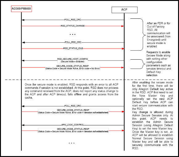
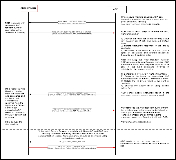
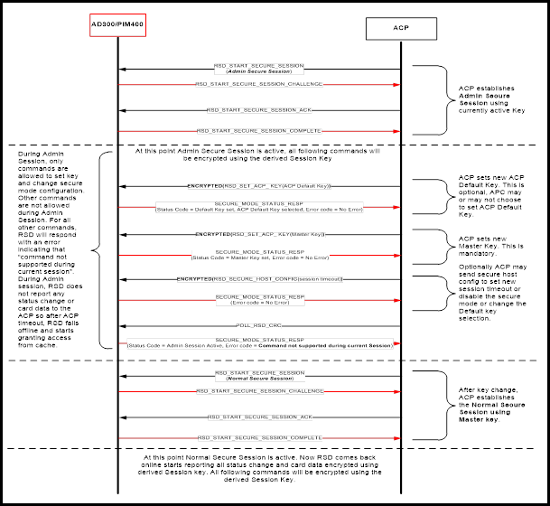
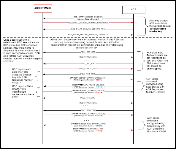
FIPS 201-2 is the federal government standard for the Personal Identity Verification (PIV) of Federal Employees and Contractors. This standard applies to identify management and physical access control for federal facilities. The government manages an Approved Products List (APL) for physical access control products that can be install in federal facilities. For an AD to be listed on the APL the AD must complete testing at a government test lab. Each system configuration must be tested individually, meaning that every PACS that integrates with AD must acquire its own approval to be listed on the APL.
In a FIPS 201-2 system the PIV card and the panel’s authentication module are performing the security functions to validate the card. During the authentication process, the AD device is passing data back and forth between the PIV card and the panel. Specific commands have been developed for the RSI protocol to support FIPS 201-2 PIV card authentication.
The AD device supports single factor authenciation (PKI-CAK) as definded by the FIPS 201-2 standard. An AD device with keypad can provide a PIN to the PACS, but this is separate from the dual factor authentication (PKI-CAK + PIN) defined by the FIPS 201-2 standard. PKI-CAK + PIN requires a contact chip reader which is not supported by AD devices.
The authentication process is as shown in Figure 10-1 below:
A user presents a PIV card to the device.
The device reads the FASC-N from the card and transmits the 200-bit FASC-N to the panel.
The panel’s authentication module sends a challenge command to the device which sends the challenge command to the PIV card.
The PIV card signs the challenge value and returns a response to the device which sends the response to the panel.
The authentication module determines if the response is valid.
The ACP makes an access control decision and sends an unlock command to the device.
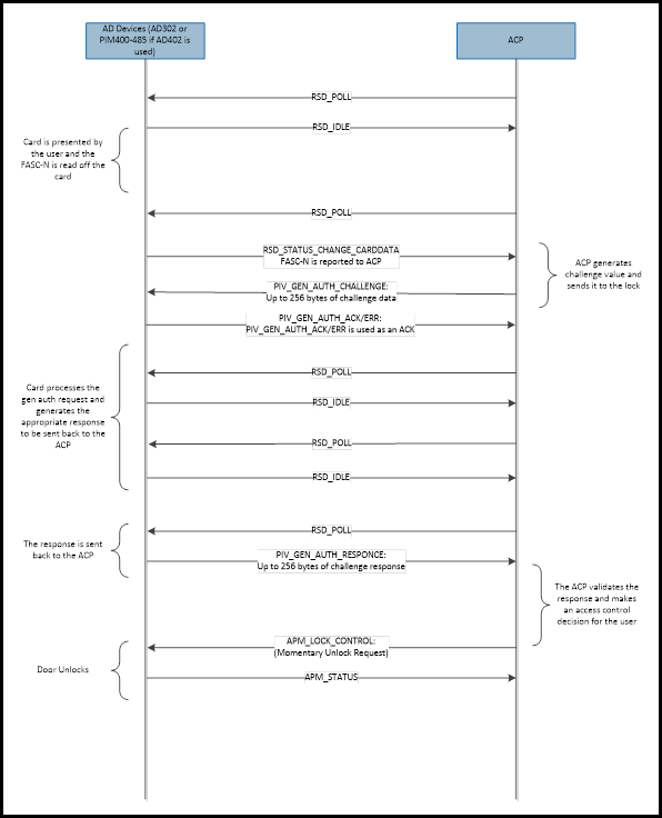
In addition to the full authentication process described above a possible use case is that the device only needs to provide the FASC-N to the panel. It is up to the discression of the facility to determine when PKI-CAK authentication is needed at an entry points and when FASC-N only authentication is acceptable.
For FASC-N only authentication the process is shown in Figure 10-2 below:
A user presents a PIV card to the device
The device reads the FASC-N from the card and transmits the 200 bit FASC-N to the panel
The panel determines if the FASC-N is valid
The panel makes and access control decision and sends an unlock command to the device.
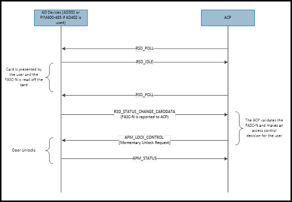
The AD device includes a configuration to switch the reader between the two authentication modes; FIPS 201-2 authentication and FASC-N only authentication.
To enable FIPS 201-2 authentication, use the SET_NEXT_GEN_APM_CONFIGURATION command to set Byte 14 bit 1 to 1. The default value for FIPS 201-2 authentication is disabled (Byte 14 bit 1 is set to 0).
The Allegion series of Networked devices use the implicit NACK mechanism for handling invalid or badly formed commands. If an RSD/APM device receives a command with an unsupported message type or a corrupted message that does fail the CRC check, the device disregards the command. The message is simply thrown away and the ACP retries with the same command if no response was received.
If the ACP does not get a response to a command within a short time window, it is expected that the ACP retransmits the same command.
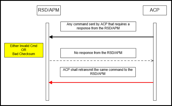
There are several command messages that are supported or available due to backward compatibility with legacy products. Some of the messages are redundant. Table 12-1 shows the recommended message to use for the management of AD-Series devices in place of the older legacy messages that are used to manage legacy devices (WA-Series, VIP-Series).
| Legacy Command/Message | Recommended Message | Descriptions |
|---|---|---|
| POLL_APM_CHECKSUM | POLL_APM_CRC | The original spec recommended the use of the checksum over the CRC because it was simpler, and it is one byte shorter. Most of IR internal testing is done with the CRC. The CRC is more reliable, so it is recommended. |
| POLL_RSD_CHECKSUM | POLL_RSD_CRC | Same as POLL_APM_CHECKSUM |
| GET_APM_DATALOG | POLL_RSD_CRC | If there is a datalog message, sending POLL_RSD_CRC gets either a RSD_STATUS_CHANGE or RSD_STATUS_CARDDATA message, which has more information than what a NEXT_DATALOG message would have. |
| SET_POLL | SET_RSD_CONFIGURATION | SET_RSD_CONFIGURATION is supported in the AD-300 and the PIM-400-485. SET_POLL is only supported in the PIM-400-485. It is best to use the common command. SET_RSD_CONFIGURATION can set the APM addresses as well as the RSD address. |
The ENGAGE products have adapted to the RSI protocol, however there are some differences with the behavior of the products that are noted herein.
Hardware Differences:
The ENGAGE products do NOT support the exact same hardware options as compared to NDE, which means the response to hardware configurations is different.