Allegion Developer Portal
Allegion Developer Portal

| REVISION CONTROL RECORD | |||
|---|---|---|---|
| VER | DATE | DESCRIPTION OF CHANGE | AUTHOR |
| 0.01 | 10/29/2018 | Initial Draft | T. Stuart |
| 0.02 | 11/01/2018 | Formatted document into Allegion standard MS Word document template and edited for grammar, etc. | A. Clark |
| 0.03 | 11/12/2018 | Incorporated most of Troy Stuart’s comments. Added Section 1.3 to Set USB mode and made more edits. | A. Clark |
| 0.04 | 12/21/2018 | Added Pre-requisites section (2.1) under the “API Changes” header | D. Shetty |
| 0.05 | 01/11/2019 | Updated document for the following updates - Handling of the driver token in the API (section 2.2.1.3) - Including examples for creating driver token and API response (section 2.2.1.1) - Including example for existing method of primary credential encryption (section 2.3.1) | D. Shetty / H. Jain / P. SA |
| 0.06 | 01/15/2019 | Reviewed updates for grammar, edits, and consistent formatting for pre-release. | A. Clark |
| Abbreviation | Definition |
|---|---|
| AES 256 | Advanced Encryption Standard utilizing a key length of 256 bits |
| API | Application Program Interface – The interface provided by the ENGAGE enabled devices and Web Application |
| BLE | Bluetooth Low Energy |
| Commission | Process in which the device gets a replaceable encryption key (REK) or the site key. |
| Db or DB | Database |
| Device | Generic term to refer to any lock, reader, or other ENGAGE component. |
| Edge Device | Any ENGAGE enabled device used for access control such as an NDE or LE lock. |
| ENGAGE | Connectivity Platform Technology |
| FDR | Factory Default Reset |
| Host or Host Server | An Alliance Partner server, external server outside of the Allegion domain |
| HTTP | Hypertext Transfer Protocol |
| HTTPS | HTTP Secure, or HTTP over SSL |
| Installer | The person who installs the ENGAGE device. These individuals will most likely be the ones also commissioning the device. These installers may or may not work for the Service Provider. There are situations where unions dictate where installers come from. |
| IP | Internet Protocol |
| JS Driver App | Desktop Application for USB data transfer from MT20W to PC |
| JSON | Java Script Object Notation |
| LAN | Local Area Network |
| MAPP | Mobile Application |
| Mobile Device | A handheld computer that is made for portability. (i.e. tablets, smart phones, iPads, etc.) |
| NDE | ENGAGE™ Wireless Cylindrical Lock |
| OPEN | A security protocol in which credentials between an access point and a client need not be exchanged |
| PEK | Production Encryption Key, generated during the manufacturing process and unique to each edge device |
| SAM | Allegion ENGAGE Software Alliance Member |
| Site | Logical grouping of ENGAGE devices which all share the same site key. In Engage this is referred to as a facility. |
| Site Key | The site key is a key that is used on all Engage enabled devices on a site, (e.g. In a building or on a floor in a building). |
| SSL | Secure Sockets Layer, a standard security technology which allows encrypted links to be established between nodes is a network |
| TLS | Transport Layer Security, cryptographic protocol allowing for secure communications |
| URI | Uniform Resource Identifier |
| URL | Uniform Resource Locator |
Prior to this feature, all data transfer between the MT20W Enrollment Reader and the Host Server was conveyed via WiFi. WiFi stability is a concern for proper MT20W operation in some facilities. To overcome this issue, the new MT20W Direct USB Feature is introduced.
The scope of this document is to provide a description of the MT20W Direct USB Feature and the changes that need to be made to the ENGAGE API to support communication between the MT20W and Host Server over USB via the ENGAGE Desktop Application.
The MT20W is detected by the JS Driver App (Desktop Application) installed on your PC. This makes use of USB communication to do data transfer. Any form of data that was previously exchanged via WiFi can now be sent to the Desktop Application via USB.
The design transfers all WiFi based communication to the USB of the MT20W device. The Desktop Application receives the information from the device (MT20W) and makes appropriate HTTP calls over the Desktop’s internet connection. Since this application does not understand the information that is being exchanged (i.e. URL, AuthToken, method to use.), the MT20W provides the data in a format which helps the Desktop App make the appropriate calls.
The MT20W firmware builds all the HTTP requests in the JSON format and transmits over USB to the Desktop Application. Similarly, the Desktop Application collects the received http responses and sends them to the MT20W in JSON format.
If your MT20W is already Commissioned at your site, there are two ways to confirm the MT20W firmware version. You can either use your desktop application or your mobile application.
NOTE: For USB communication, the MT20W firmware must be at version 39.02.00 or higher.
To verify the current MT20W firmware revision:
Open the ENGAGE Web Application on your desktop.
Navigate to the ADVANCED tab.
Select Firmware.
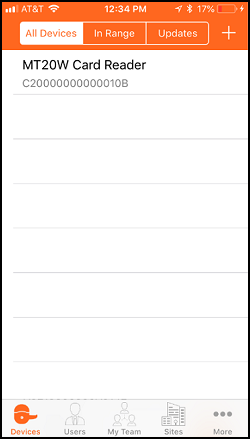
Locate the MT20W device in the Device List.
View the MT20W Current Firmware Version versus the Latest Firmware Version.
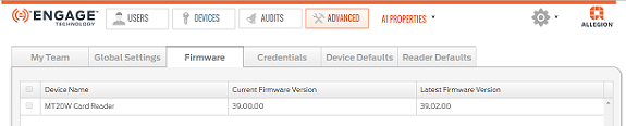
NOTE: In this case the MT20W firmware is not at the latest revision.
This process assumes that there is a WiFi network already saved and available for use by the mobile application.
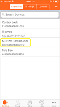
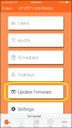
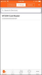
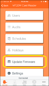
Verify the MT20W has latest Firmware by following steps 1 through 3 below:
| 1. Select MT20W device | 2. Select Update Firmware | 3. Is Firmware Current? |
|---|---|---|
 |  | 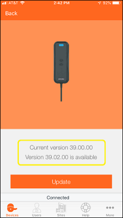 |
When the current firmware version is earlier than version 39.02.00, you must update the firmware when using USB communication.
Click on the Update button from the mobile app to update the firmware.
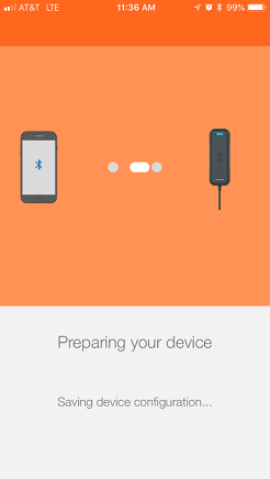
The Initiating firmware download screen displays.
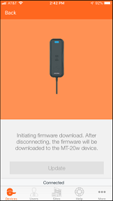
The firmware is downloaded to the MT20W.
The Installing firmware screen displays.

Click Finish.
The blank In Range mobile display is shown.
![]()
The MT20W automatically finishes its firmware installation process and reboots. Be patient, this may take a few minutes. Wait for all LED flashing to stop.
The boot-up process is complete and the MT20W is communicating when a solid BLUE LED displays.
The mobile app screen does not update again until the User swipes down to refresh the screen or navigates away and comes back to the All devices or In Range screen.
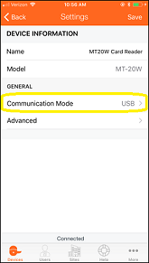
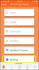
| a. Select Settings | b. Select Comm Mode | c. Select USB Mode |
|---|---|---|
 |  |  |
MT20W light interpretation remains the same.
The Desktop Application acts as a transmitter/receiver between the MT20W and the ENGAGE Web Application.
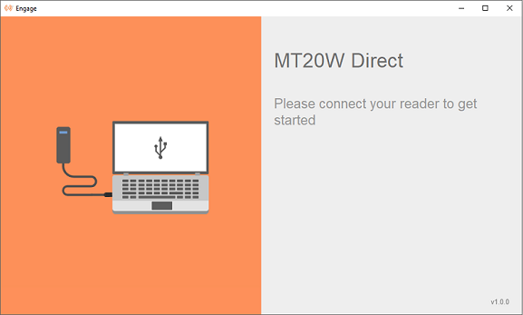
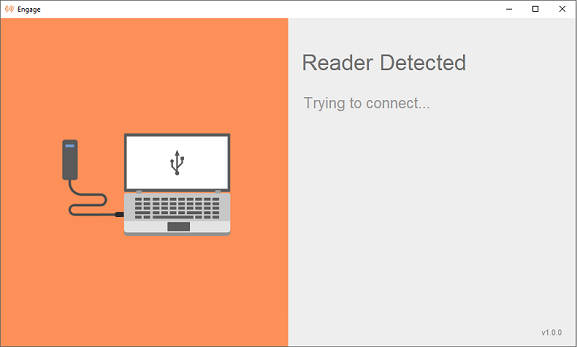
On opening the ENGAGE Desktop Application, the information on the screen instructs you to connect the MT20W to your PC to get started (Figure 1).
Figure 1: MT20W Direct
Once you plug the MT20W into the USB port on the PC, the ENGAGE Desktop Application detects the reader and begins communication (Figure 2 & 3).
NOTE: The ENGAGE Application does not start automatically when the MT20W is first connected. When using USB communication, the ENGAGE Desktop Application must be running.
After power up, the MT20W must go through a boot up process BEFORE a connection is accomplished. Be patient, this may take a few seconds.
Figure 2: Reader Detected

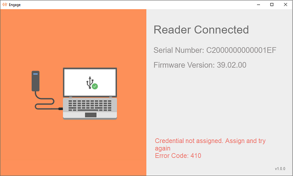
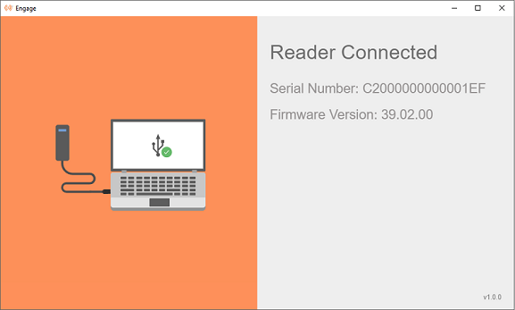
After the connection is established, the serial number and firmware version of the ENGAGE Desktop Application displays on the screen (Figure 3).
Figure 3: Reader Connected

NOTE: If you close the ENGAGE Desktop Application on the PC by clicking on the ‘X’ in the upper right-hand corner, you must restart it again before USB communication is available. The MT20W shows a solid RED LED in this case.
The ENGAGE Icon symbol
shows in your PC system tray anytime the ENGAGE Application is running.
If any error occurs during the communication, an error message along with the error code displays on the screen along with a notification (Figure 4).
Figure 4: Error Detected
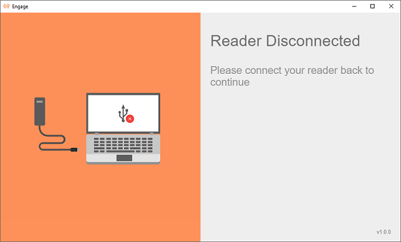
When the reader is un-plugged from the Desktop/System, the Application screen shows that the reader is disconnected (Figure 5).
Figure 5: Reader Disconnected
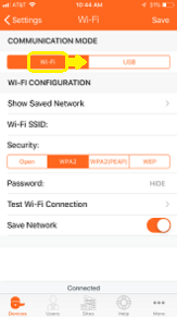
If you intend to use WiFi instead of USB Direct Mode, and the MT20W has already been commissioned in an earlier process, perform the following steps to enable WiFi.
WARNING: A Saved Network MUST be locally available at the location where the device is being installed and commissioned. Be sure a saved WiFi network is present and locally available before selection.
If there are no saved WiFi networks, a new network MUST be added. (see the Adding a new WiFi Network section).
When a Saved Network is available, the property administrator may select that WiFi network for quick and accurate data entry.
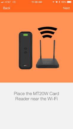
Ensure the Schlage MT20W is in signal range of the local WiFi network access point.
Select Next.
Confirm the Schlage MT20W Credential Reader selected for Commissioning.
| a. Select Settings | b. Select Comm Mode | c. Select WiFi Mode |
|---|---|---|
 | | 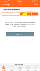 |
| No Saved WiFi Networks | One Saved WiFi Network Available |
|---|---|
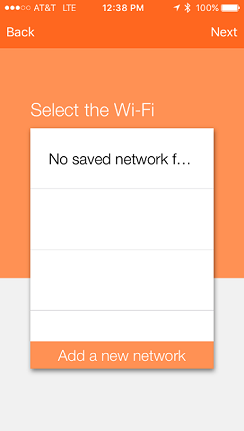 |  |
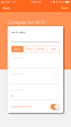
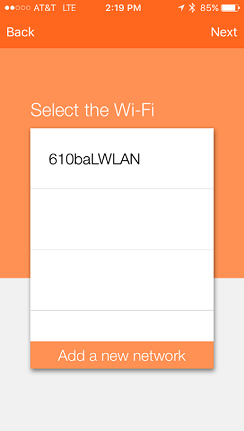
Enter the WiFi SSID.
This is the name of the local wireless local area network
This entry must be EXACT and is CASE SENSITIVE
Select the WiFi Security used by the local area wireless network
NOTE: Depending on the WiFi network security chosen, you may need to enter different information. Those items highlighted in the screen below (not grayed out) are required.
In this case we chose WiFi SSID 610baLWLAN and the WPA2 (PEAP) network security protocol. Both a Username and Password are required.
NOTE: The WiFi network settings can now be programmed into the Schlage MT20W and the Schlage MT20W connects to the local WiFi network using the entered network settings. Wait a few moments until the Schlage MT20W provides a solid Blue LED indicating it has successfully connected with the local wireless area network.
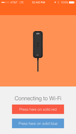
WARNING: If the Schlage MT20W does not provide a solid Blue LED and tries to reconnect but fails, the WiFi network settings are not entered correctly or the local WiFi network is not present.
HINT: You can also verify the local network security settings by using your Mobile Phone to enter the network settings and temporarily connect to verify local WiFi network connection requirements.
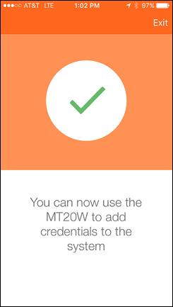
Acknowledge the “Setup Complete” message.
Select Exit.
VERIFY SUCCESS
NOTES:
The Schlage MT20W solid BLUE “Connected” LED display indicates the Schlage MT20W is connected to the local wireless WiFi network and operating properly.
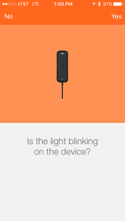
The Schlage MT20W flashes BLUE quickly while trying to connect with the local WiFi network.
When the local WiFi network connection fails, the Schlage MT20W displays a solid RED LED.
When the local WiFi network is not available (failed or down for maintenance), the Schlage MT20W automatically retries to reconnect to the local WiFi network every few minutes.
 | then… | |
|---|
NOTE: The Schlage MT20W resets and tries to connect to the local WiFi network using the saved network settings. Be patient, wait a few moments while the Schlage MT20W tries to connect to the local WiFi (fast Blue LED blinking) and then provides a solid Blue LED indicating it has successfully connected to the local WiFi network.
WARNING: If the Schlage MT20W does not provide a solid Blue LED and tries to reconnect but fails, the WiFi network settings are not correct or the local WiFi network is not present.
HINT: You can also verify the local network security settings by using your mobile phone to enter the network settings and temporarily connect with your phone. When successful, the local WiFi network connection requirements are verified and can be re-entered as a saved network.
After the Send Link button is selected, the system sends a link to your email. Go to your email and follow the instructions.


Select Windows or macOS operating system button.
Navigate to the PC “Download” folder.
Locate the Engage_Setup installation application.

NOTE: PC Administration authority (permissions) are required.
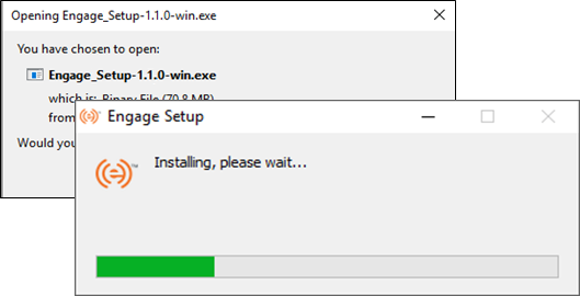
When the installation is successful, the following screens display on the desktop.
Reader Detected
After the connection is established, the serial number and firmware version of the application displays on the screen.
Reader Connected
NOTE: Do NOT close this application.
There are changes to existing API integrations that need to be made to use the MT20W Direct USB Feature.
All communication between the Desktop Application and the host server is over HTTPS(i.e. communication is secure/encrypted). For this you need to install an SSL certificate onto the web server to initiate a secure session with the Desktop Application. SSL proves to the user that they are really connecting to the site they requested, and not to an attacker masquerading as the end site.
NOTE: Regardless of whether ‘Secured’ or ‘Unsecured’ configuration is selected during MT20W setup, the communication is ‘Secured’ (using HTTPS) between the host server and the Desktop Application. Thus, a valid SSL certificate for the web server is required.
SSL certificates are bound to a ‘common name’, which is usually a fully qualified domain name but sometimes are a wildcard name (e.g. *.domain.com) or even an IP address. The configuration (‘DNS’ name or ‘IP’ address) entered for the MT20W must match the ‘common name’ provided in the certificate or the connection between the web server and Desktop Application fails.
The APIs should now support a new authentication scheme called Driver. All MT20Ws that are commissioned in the USB mode use this Driver authorization scheme header (i.e. Authorization: Driver {token}) to communicate with the APIs. The MT20Ws that are in WiFi mode continue to use the existing Device authorization scheme.
If the MT20W is in USB mode and tries to call the API with Device authorization scheme (i.e. Authorization: Device {token}) instead of Driver authorization scheme, the API sends back a 401-Unauthorized message.
The Driver token is a combination of the serial number of the device and a timestamp (or random number). See the details below on how the driver token is generated from the firmware.
The following algorithm is used in the MT20W firmware to generate the driver token.
Append 16-byte random number or timestamp (i.e the value of response header 'X-Device-Last-Connected') to the 16-byte serial number. The total length = 32-bytes (16-bytes number + 16-bytes SN). Reference the Section: Handling Driver Token from the API for more details about 'X-Device-Last-Connected'.
A sample random number could be 20180919105017.
Encrypt this 32-byte data with the site key. This encrypted value is appended with the serial number.
Encode the entire string to base64.
The resulting string is the auth token that is sent to the host.
Example: Consider Site Key to be BAE3B37054AFDF441390B29032417F5BF1739AE1B784BF6C6A8A9617CC5B19
Let 16-byte random number be 2019011103485600
| BitPosition | 0 | 1 | 2 | 3 | 4 | 5 | 6 | 7 | 8 | 9 | 10 | 11 | 12 | 13 | 14 | 15 |
|---|---|---|---|---|---|---|---|---|---|---|---|---|---|---|---|---|
| Data (0x) | 32 | 30 | 31 | 39 | 30 | 31 | 31 | 31 | 30 | 33 | 34 | 38 | 35 | 36 | 00 | 00 |
Let Serial number be A0C1777700000017
| BitPosition | 0 | 1 | 2 | 3 | 4 | 5 | 6 | 7 | 8 | 9 | 10 | 11 | 12 | 13 | 14 | 15 |
|---|---|---|---|---|---|---|---|---|---|---|---|---|---|---|---|---|
| Data (0x) | 00 | 00 | 00 | 00 | 00 | 00 | 00 | 00 | A0 | C1 | 77 | 77 | 00 | 00 | 00 | 17 |
Step 1: Append random number to serial number to form 32-byte data, the result would be:
| BitPosition | 0 | 1 | 2 | 3 | 4 | 5 | 6 | 7 | 8 | 9 | 10 | 11 | 12 | 13 | 14 | 15 |
|---|---|---|---|---|---|---|---|---|---|---|---|---|---|---|---|---|
| Data (0x) | 32 | 30 | 31 | 39 | 30 | 31 | 31 | 31 | 30 | 33 | 34 | 38 | 35 | 36 | 00 | 00 |
| BitPosition | 16 | 17 | 18 | 19 | 20 | 21 | 22 | 23 | 24 | 25 | 26 | 27 | 28 | 29 | 30 | 31 |
| Data (0x) | 00 | 00 | 00 | 00 | 00 | 00 | 00 | 00 | A0 | C1 | 77 | 77 | 00 | 00 | 00 | 17 |
Step 2: Encrypt 32-byte data with Site Key (AES 256 encryption), the result would be:
EF8A7F17E39973D9154E7AFDDD5EC93A8BD13710A2CA943E24CFF8AA391DB8B4
Step 3: Append Serial Number to Encrypted data, the result would be:
0000000000000000A0C1777700000017:EF8A7F17E39973D9154E7AFDDD5EC93A8BD13710A2CA943E24CFF8AA391DB8B4:1
Step 4: Encode the entire string to base64, the result would be:
MDAwMDAwMDAwMDAwMDAwMEEwQzE3Nzc3MDAwMDAwMTc6RUY4QTdGMTdFMzk5NzNEOTE1NEU3QUZEREQ1RUM5M0E 4QkQxMzcxMEEyQ0E5NDNFMjRDRkY4QUEzOTFEQjhCNDox
This is the Auth Token to be sent in the API request with Driver as prefix.
Below is an existing API that is used to transfer No Tour data to the MT20W. This API is called each time a card is presented to the MT20W reader.
API: POST /api/credentials/scan
Request Headers:
Authorization: Driver
MDAwMDAwMDAwMDAwMDAwMEEwQzE3Nzc3MDAwMDAwMTc6RUY4QTdGMTdFMzk5NzNEOTE1NEU3 QUZEREQ1RUM5M0E4QkQxMzcxMEEyQ0E5NDNFMjRDRkY4QUEzOTFEQjhCNDox
Content-Type: application/json; charset=UTF-8
Request Body:
{
"BadgeId":"65535",
"Primary":" MmBz+Li+C3Pk5GNR8oSsjWY6qa98PdTSAQS4RcbwCk=",
"CardFormat": "smart",
"Format":"Bytes"
}
Response: There is no change in the response format. It remains the same as the existing response. The only difference now is every API request that is made using Driver auth token is expected to send a response header ‘X-Device-Last-Connected’. (Ref: Handling Driver Token from the API)
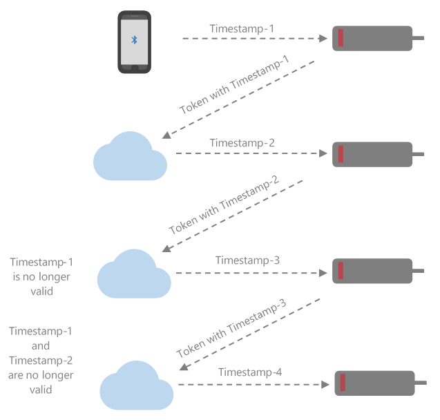
API requests from MT20W with Driver token are in USB mode. Furthermore, API requests with Driver token are always responded with an encrypted + encoded timestamp (or random number) value in the response header. The response header is X-Device-Last-Connected.
This timestamp must be unique for the consecutive requests. The MT20W uses the timestamp from the response header in the authorization token of the next request (This is done to ensure dynamic token generation. Since the messages are now exchanged over USB with the Desktop application, dynamic tokens are necessary to avoid record and replay attacks).
It is recommended that the API keep the information of the timestamp sent in the response header and perform an equality check during the next request (This is to ensure the authorization tokens are always unique and previous authorization tokens are always invalid, to avoid any request replays). However, for the very first request from the MT20W, this check cannot be done as the host does not have the information of the timestamp used in the token, which would be acceptable.
NOTES:
Here timestamp must be a 14-digit number. You could use any 14-digit random number as long as consecutive requests do not have the same value for this number.
The timestamp is encrypted with the siteKey and encoded in base64 format and sent as ‘X-Device-Last-Connected’ response header value.
The existing validation check remains as it is (i.e. Serial number validation, commissioned or not validation etc.)
There were some enhancement changes made to security by introducing changes to the encryption of the Primary credential which is part of the API request body.
NOTE: This is still applicable for WiFi mode of operation.
Primary credential is 8 bytes (16 hex digits) in length.
The credential value is filled with b0s until the byte boundary and 0xFF for the rest of the bytes (to form an 8 byte credential ID)
MT20W fills 0xFF as the most significant 8 bytes to form a 16 byte (128 bits) block of data for encryption
MT20W encrypts (AES 256) the 16 bytes (from step 2) using the Site Key as the encryption key and zeros for Init Vector.
This encrypted value (16 bytes OR 32 hex digits) is encoded in Base 64 format (24 bytes) and sent as the Primary credential data to ORCA.
ORCA decodes the Base 64 encoded data and then decrypts the Primary value from step 4, using the site key as the decryption key and zeros for Init Vector.
The decryption results in a 16 byte (32 hex digits) data and ORCA pulls the least significant 8 byte to get the Primary Credential value.
| Bit position | 0 -7 | 8-15 |
|---|---|---|
| Data | Raw card data | 0xFF |
Raw card data as printed on the card: 0x9400016009A4
| Unencrypted data | Encrypted data | Encoded data | Site Key | |||||||
|---|---|---|---|---|---|---|---|---|---|---|
| Bit position | Data | Bit position | Data | Bit position | Data | Bit position | Data | |||
| 0 | 0x94 | 0 | 0xEB | 0 | 0x36 | 0 | 0xD4 | |||
| 1 | 0x00 | 1 | 0x10 | 1 | 0x78 | 1 | 0xBE | |||
| 2 | 0x01 | 2 | 0x94 | 2 | 0x43 | 2 | 0x94 | |||
| 3 | 0x60 | 3 | 0xDA | 3 | 0x55 | 3 | 0x94 | |||
| 4 | 0x09 | 4 | 0x0B | 4 | 0x32 | 4 | 0xB8 | |||
| 5 | 0xA4 | 5 | 0xCE | 5 | 0x67 | 5 | 0x3F | |||
| 6 | 0xFF | 6 | 0x42 | 6 | 0x76 | 6 | 0xF0 | |||
| 7 | 0xFF | 7 | 0xE5 | 7 | 0x4F | 7 | 0xC0 | |||
| 8 | 0xFF | 8 | 0x9E | 8 | 0x51 | 8 | 0x18 | |||
| 9 | 0xFF | 9 | 0x41 | 9 | 0x75 | 9 | 0x87 | |||
| 10 | 0xFF | 10 | 0xB7 | 10 | 0x57 | 10 | 0x24 | |||
| 11 | 0xFF | 11 | 0xCF | 11 | 0x65 | 11 | 0xE2 | |||
| 12 | 0xFF | 12 | 0xEF | 12 | 0x51 | 12 | 0x56 | |||
| 13 | 0xFF | 13 | 0x51 | 13 | 0x62 | 13 | 0xC9 | |||
| 14 | 0xFF | 14 | 0x8F | 14 | 0x66 | 14 | 0xEE | |||
| 15 | 0xFF | 15 | 0x4A | 15 | 0x50 | 15 | 0x51 | |||
| 16 | 0x37 | 16 | 0x1D | |||||||
| 17 | 0x31 | 17 | 0x40 | |||||||
| 18 | 0x47 | 18 | 0x07 | |||||||
| 19 | 0x50 | 19 | 0x6A | |||||||
| 20 | 0x53 | 20 | 0x52 | |||||||
| 21 | 0x67 | 21 | 0xA0 | |||||||
| 22 | 0x3D | 22 | 0x82 | |||||||
| 23 | 0x3D | 23 | 0xC5 | |||||||
| 24 | 0x00 | 24 | 0xDE | |||||||
| 25 | 0x9D | |||||||||
| 26 | 0x30 | |||||||||
| 27 | 0xF3 | |||||||||
| 28 | 0x5B | |||||||||
| 29 | 0x16 | |||||||||
| 30 | 0x85 | |||||||||
| 31 | 0x28 |
The Primary credential is 8-bytes (16 hex digits) in length. The following steps are used to encrypt the Primary credential:
The credential value is filled with binary bit 0s up to the byte boundary and 0xFF for the rest of the bytes (to form an 8-byte credential ID).
The MT20W fills 0xFF as the most significant 8-bytes to form a 16-byte (128 bits) block of data.
A random number of 12 bytes is generated and used as the first part of data to be encrypted. This is followed by the Primary credential of 16-bytes mentioned in the previous step.
Two additional bytes of 0x00s are added to the data to make it 30-bytes long.
CRC is calculated on this entire data and placed in the last two bytes of the 32-byte unencrypted data array.
The MT20W encrypts (AES 256) the 32-bytes (from above step) using the Site Key as the encryption key and zeros for Init Vector.
This encrypted value (32-bytes OR 64 hex digits) is encoded in Base64 format (44-bytes) and sent as the Primary credential data to ORCA.
| Bit position | 0 -11 | 12-19 | 20-27 | 28-29 | 30-31 |
|---|---|---|---|---|---|
| Data | 12-byte Random number | Raw card data padded with 0xFF to form 8 bytes | 0xFF | 0X00 | CRC-16 |
Raw card data as printed on the card: 0x9400016009A4.
| UNencrypted data | Encrypted data | Encoded data | Site Key | |||||||
|---|---|---|---|---|---|---|---|---|---|---|
| Bit position | Data | Bit position | Data | Bit position | Data | Bit position | Data | |||
| 0 | 0xAE | 0 | 0x51 | 0 | 0x55 | 0 | 0xD4 | |||
| 1 | 0xB0 | 1 | 0xAF | 1 | 0x61 | 1 | 0xBE | |||
| 2 | 0x8A | 2 | 0x52 | 2 | 0x39 | 2 | 0x94 | |||
| 3 | 0xF2 | 3 | 0x14 | 3 | 0x53 | 3 | 0x94 | |||
| 4 | 0x44 | 4 | 0xA6 | 4 | 0x46 | 4 | 0xB8 | |||
| 5 | 0x7E | 5 | 0xB5 | 5 | 0x4B | 5 | 0x3F | |||
| 6 | 0x0C | 6 | 0xF0 | 6 | 0x61 | 6 | 0xF0 | |||
| 7 | 0x7C | 7 | 0xBC | 7 | 0x31 | 7 | 0xC0 | |||
| 8 | 0xF8 | 8 | 0xDA | 8 | 0x38 | 8 | 0x18 | |||
| 9 | 0xF5 | 9 | 0x59 | 9 | 0x4C | 9 | 0x87 | |||
| 10 | 0x3A | 10 | 0xE6 | 10 | 0x7A | 10 | 0x24 | |||
| 11 | 0x3B | 11 | 0xCB | 11 | 0x61 | 11 | 0xE2 | |||
| 12 | 0x94 | 12 | 0x11 | 12 | 0x57 | 12 | 0x56 | |||
| 13 | 0x00 | 13 | 0xA3 | 13 | 0x65 | 13 | 0xC9 | |||
| 14 | 0x01 | 14 | 0xD6 | 14 | 0x62 | 14 | 0xEE | |||
| 15 | 0x60 | 15 | 0xC9 | 15 | 0x4C | 15 | 0x51 | |||
| 16 | 0x09 | 16 | 0x80 | 16 | 0x45 | 16 | 0x1D | |||
| 17 | 0xA4 | 17 | 0x63 | 17 | 0x61 | 17 | 0x40 | |||
| 18 | 0xFF | 18 | 0x0E | 18 | 0x50 | 18 | 0x07 | |||
| 19 | 0xFF | 19 | 0x5D | 19 | 0x57 | 19 | 0x6A | |||
| 20 | 0xFF | 20 | 0xAA | 20 | 0x79 | 20 | 0x52 | |||
| 21 | 0xFF | 21 | 0xA6 | 21 | 0x59 | 21 | 0xA0 | |||
| 22 | 0xFF | 22 | 0xBE | 22 | 0x42 | 22 | 0x82 | |||
| 23 | 0xFF | 23 | 0x45 | 23 | 0x6A | 23 | 0xC5 | |||
| 24 | 0xFF | 24 | 0x22 | 24 | 0x44 | 24 | 0xDE | |||
| 25 | 0xFF | 25 | 0xCA | 25 | 0x6C | 25 | 0x9D | |||
| 26 | 0xFF | 26 | 0xFC | 26 | 0x32 | 26 | 0x30 | |||
| 27 | 0xFF | 27 | 0x43 | 27 | 0x71 | 27 | 0xF3 | |||
| 28 | 0x00 | 28 | 0xA5 | 28 | 0x70 | 28 | 0x5B | |||
| 29 | 0x00 | 29 | 0x44 | 29 | 0x72 | 29 | 0x16 | |||
| 30 | 0XE9 | 30 | 0x42 | 30 | 0x35 | 30 | 0x85 | |||
| 31 | 0x4C | 31 | 0xE9 | 31 | 0x46 | 31 | 0x28 | |||
| 32 | 0x49 | |||||||||
| 33 | 0x73 | |||||||||
| 34 | 0x72 | |||||||||
| 35 | 0x38 | |||||||||
| 36 | 0x51 | |||||||||
| 37 | 0x36 | |||||||||
| 38 | 0x56 | |||||||||
| 39 | 0x45 | |||||||||
| 40 | 0x51 | |||||||||
| 41 | 0x75 | |||||||||
| 42 | 0x6B | |||||||||
| 43 | 0x3D | |||||||||
| 44 | 0x6D |
API must decode Base 64 and decrypt the Primary value using the site key as the decryption key. The decryption results in a 32-byte (32 hex digits) data and API pulls the masked 8-bytes to get the Primary Credential value.
The following steps are used to decrypt the Primary credential:
Decode the base64 formatted Primary credential.
Decrypt the decoded data using the Site key. This results in 32-byte un-encrypted Primary credential (Byte array of Hex values).
The last two bytes of this array contains CRC. This CRC follows [LSB, MSB] format, hence reverse the CRC byte array.
Compute the CRC16 for the first 30 bytes excluding the CRC.
Compare the CRC obtained with the CRC of incoming request. If the CRC check fails, then API returns Bad Request with a message Credential data is corrupt.
Once the CRC check is passed, Primary data (Total of from Byte[12] to Byte[27] – includes raw card data (8bytes) and padded 0xFF(8bytes)), is extracted from UNencrypted data. (See the Section: Encryption Changes for Primary Credential).
This is the method used to compute CRC. 0x10FFFF is used for masking in CRC 16 calculation and 0x1021 is the polynomial used.
public uint ComputeCrc16(byte [] bytes)
     {
       uint crc = 0;
       foreach (byte b in bytes)
       {
         crc ^= (uint) (b << 8);
         for (int i = 0; i < 8; i++)
         {
           if ((crc & 0x8000)! = 0)
           {
             crc = (((crc << 1) & 0x10FFFF) ^ 0x1021);
           }
           else
           {
             crc <<= 1;
           }
         }
       }
       return crc;}